Influencing the profile of the properties of a web by means of at least one acoustic field

a technology of acoustic field and a web, applied in the direction of papermaking machines, spray discharge apparatus, textiles and paper, etc., can solve the problems of inability to “grab”, insufficient possibility, and inability to influence, so as to improve the orientation of the fibers in consecutive formers, reduce the shearing stress in the coating color, and improve the glide relative

Inactive Publication Date: 2006-07-20
RONNENBERG DIETER
View PDF23 Cites 7 Cited by
  • Summary
  • Abstract
  • Description
  • Claims
  • Application Information

AI Technical Summary

Benefits of technology

[0024] An another advantage of the invention is that the influencing of fiber orientation and the influencing of basis weight cross profile in the headbox are as independent from each other as possible. In other words, by means of the invention the fiber orientation (sectional) is possible alone with a directed sound field, while the headbox controls only the desired basis weight cross profile. It is also intended that by use of a sectional density controlled headbox, the fiber orientation in the consecutive former can improved by the present invention.
[0025] But not only fibers can be aligned with a directed sound field: generally color particles haven't a sphere form. The kaolin used in paper production has a lamella like structure. By reason of the above mentioned facts it is understandable that color particles can also be aligned by the proposed method. If the color particles—or, for example, little metal plates—are mixed into the suspension and the wave fronts are parallel to the surface of the fiber web, so the particles or the little metal plates will also undergo a parallel orientation to the surface of the fiber web. If the sound field in this embodiment does not effect the whole width of the fiber web, a colored signature in the fiber web is possible, which is translucent in the dry fiber web. If the sound field additionally is oscillating and / or intermitting, so line shaped or pattern shaped signatures can be designed. This has the advantage that, for example, paper documents and also paper money can be provided with a kind of signature, which is positioned inside the paper and not printed on the paper and therefore exceptionally counterfeitproof. But in this way the fibers are also alignable so that, for example, with a special lamp the inventive signature can be read or checked. This method of reading works by light reflection and / or light transition.
[0026] Color particles in the sump of a coating machine or color particles at the surface of a fiber web in a coating machine can also be aligned, by means of the invention, parallel to the fiber web surface. There is the advantage that the irregular color plates can be aligned in layers and therefore the aligned plates can better glide relative to each other at the coating operation or the doctoring process. This means that the shearing stress in the coating color can be reduced by the invention. By this gliding, the color particles don't hook together or don't block, which otherwise would create a thicker and above all an irregular coating film. A positive side effect is that the sound field in the sump of a coating machine can destroy color lumps and / or can remove containing gases out of the coating color.
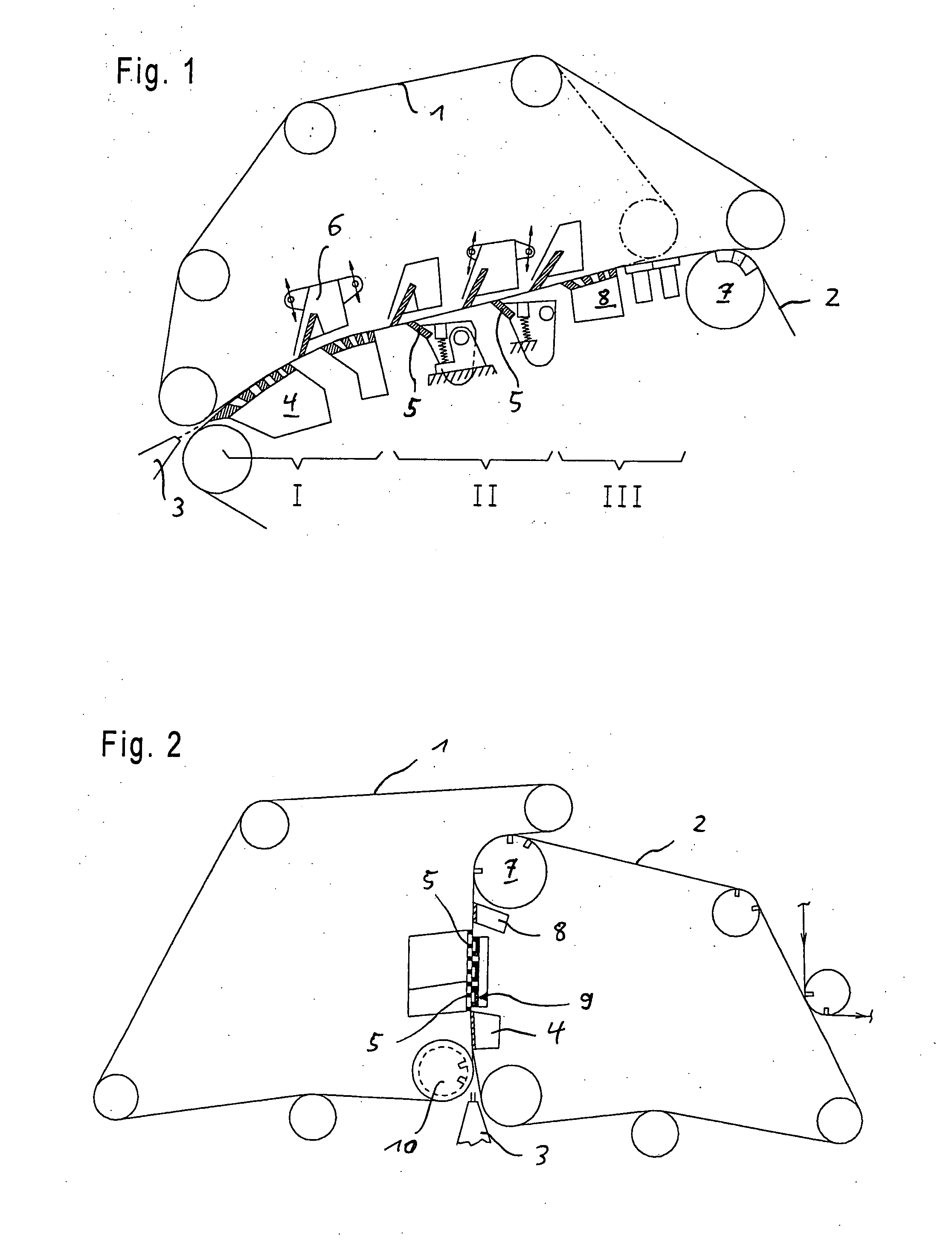
[0027] A further, very essential advantage of the invention is that the spreading speed of a sound field in a liquid amounts to nearly 1500 m / s, but the working speed of a modern paper machine is only 30 m / s. If a sound field, for example, has a width of 100 mm (in the running direction of the fiber web) and a frequency of 20,000 Hz, so the fibers are influenced by a total 67 vibrations in their run over the sound field. In comparison to the formers of the prior art with their limited number of slats (dewatering ledges), the inventive use of the sound field presents a much higher number of pulses, wherein the pulses / vibrations not only influence the dewatering, but also influence selectively the orientation of fibers and other particles. This just mentioned advantage can be heightened, if the chosen frequency is substantially higher. Because the inventive device—in view of the running direction—is very narrow, either it is possible to place the device between two slats or to place instead of few slats (dewatering ledges). So at least the number of ledges substantially remains the same.
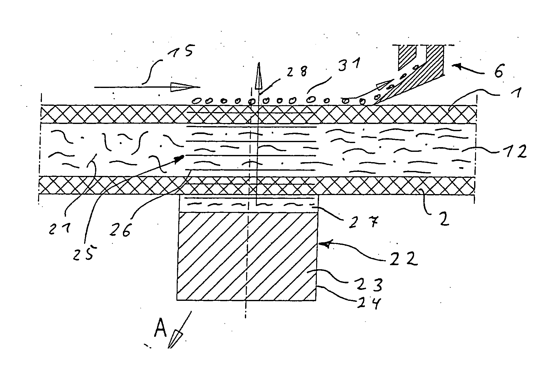
[0028] The inventive sound fields are generated by an electric powered emitter. Every emitter consists of a power unit and a housing. The drive is created by a coil, a magnetic piston and a membrane or by piezo elements or the drive works on the magnetostrictive or capacitive principle. The surface of the power unit which emits the sound field does generally has a parallel stroke. Because the emitters are electrically driven, their power units can be designed by means of electro-technics and electronics in manifold ways. By using a central 
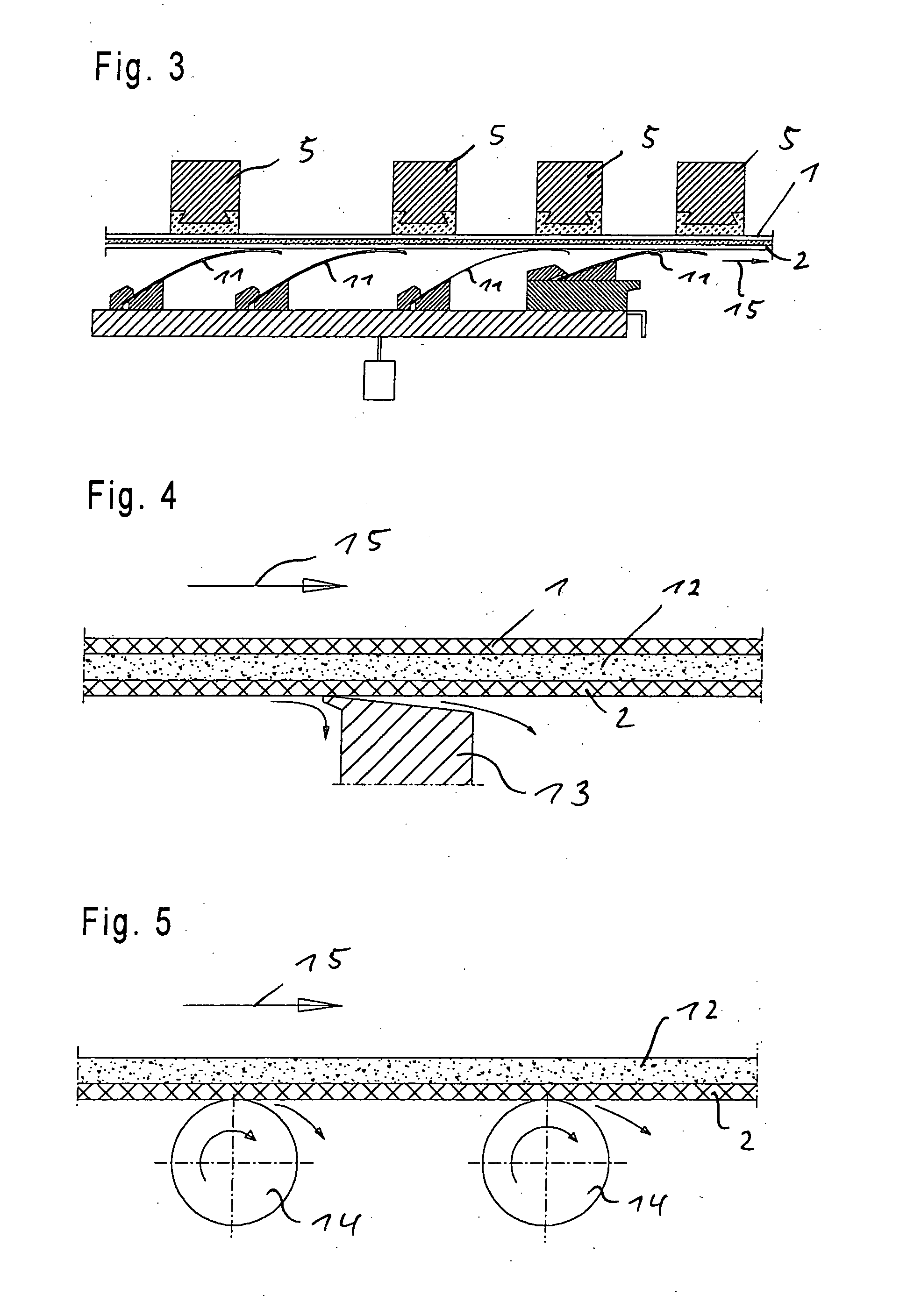
control unit, vibrations for each power unit are individually adjustable. By superposition of vibrations, periodic pulses can also be generated. The vibrations will be defined, for example at the control unit, in their amplitude, phase, frequency and energy. So that for every power unit a separate cable need not be laid, it is particularly advantageous, if the control occurs by means of a central data bus. Because with a paper machine several kinds of paper will be produced and therefore a lot of production parameters are necessary, it is advantageous, if the parameters of the inventive device are stored in a database of the control unit. If production of a specific kind of paper with know parameters will be restarted, the parameters will be reloaded from the storage. Production costs are reduced due to this increased efficiency. Further it is advantageous if the control unit is linked to an online-measuring system, for example, to a so called measuring frame.

Problems solved by technology

As already stated, if the suspension beam leaves the outlet of the headbox, the is only a little and an insufficient possibility for influencing the basis weight and / or the fiber orientation cross profile by the dewatering elements.
Fundamentally, this problem is based on the fiber web, which is “caught” between two wires.
Because the wires are running, it is not possible to “grab through” the wires to influence, for example, the fiber orientation.
This method of influencing is not possible, because it has to effect at least than half of the width of the fiber web.
Therefore today the influencing over the gaps is not controllable.
This lack of control also occurs, because the regions of the fiber web, which are closer to the tender or drive side, hide the more inner regions of the fiber web.
Because that area of the paper machine is a “rough” environment and a such fine material tool would not be practical, the inventor had the idea that one should send a directed energy to the meshes.
Because non insulated electrical energy in a wet environment is not practical (because of possible electric shocks), the decision was made in favor of sound energy.
Also the forms of the figures are not practicable for the influencing of a fiber web, because a homogeneity of a fiber web is desired.

Method used


Image

  • Influencing the profile of the properties of a web by means of at least one acoustic field
  • Influencing the profile of the properties of a web by means of at least one acoustic field
  • Influencing the profile of the properties of a web by means of at least one acoustic field

Examples


Embodiment Construction

[0073]FIG. 1 shows a kind of former, which is published in the above cited document EP 0489 094 A1. A suspension stream comes out of the headbox 3, which will surrounded by two wires 1, 2 and dewatered in a first dewatering line I by means of a curved dewatering element (here a forming shoe). The following dewatering line II is characterized by partly fixed and partly flexible ledges 5. The final dewatering line III consists of about at least one stationary dewatering element (for example forming shoe, suction box). The forming shoe also consists of ledges, but these ledges in contrast to the ledges 5 are a fixed components of the forming shoe 4.

[0074] In the former of FIG. 2 a former is shown, which is published in the document EP 0627 523 A1. The first dewatering element after the headbox 3 is here a forming roll 10, which follows a forming shoe 4. In a further unit are arranged double ledges 9 and simple ledges 5. The dewatering in these twin wire zones ends with a suction box 8...


PUM


Abstract

The invention relates to a method and a device for the processing of a fiber web or a suspension layer in a paper-, cardboard- or coating-machine or a size press for influencing the profile of the properties of a web by means of at least one sectional, directed acoustic (sound) field. In other words, the acoustic field is narrower than the width of the fiber web or the suspension layer, and the acoustic field affects components of the fiber web or suspension layer at a defined angle. Profiles of the properties of a web influenced by acoustic fields are lamination, spatial orientation, fiber orientation, dry content, breaking length ratio, flocculation and color coat thickness. Furthermore, the introduction of a signature mark into the fiber web or suspension layer is possible.

Description

BACKGROUD OF THE INVENTION [0001] The invention relates to a method and a device for the processing of a fiber web or a suspension layer in a paper-, cardboard- or coating-machine or a size press for influencing the profile of the properties and in this way the paper or cardboard produced. [0002] Despite the fact that the present invention under discussion is suitable for paper machines as well as cardboard machines, it will (for stylistic reasons only) be referred to throughout as a “paper machine”. The transition from a suspension layer to a fiber web in a former of a paper machine is called the “immobility point” by experts. Expert's current opinion is that the fibers do not change their orientation in the fiber web after that point. Due to the fact that the position of the immobility point cannot exactly be defined and, additionally, the fact that in the invention under discussion this point movable towards the press section, the term fiber web alone will be used in future. Thes...

Claims


Application Information

Patent Timeline
Patent Type & Authority Applications(United States)
IPC IPC(8): D21F5/00D21F7/06D21F1/00D21F1/44
CPCD21F1/009D21F1/44
Inventor RONNENBERG, DIETER
Owner RONNENBERG DIETER
Why Eureka
Try Eureka