Intake device for vehicle

a technology for vehicle intake and air intake, which is applied in the direction of machines/engines, combustion-air/fuel-air treatment, and corona discharge, etc., can solve the problems of difficulty in appropriately handling static electricity charge to the vehicle, and achieve the effect of improving the intake efficiency of intake air

Active Publication Date: 2016-04-21
TOYOTA JIDOSHA KK
View PDF5 Cites 15 Cited by
  • Summary
  • Abstract
  • Description
  • Claims
  • Application Information

AI Technical Summary

Benefits of technology

[0020]By providing the self-discharge static eliminator according to the above aspect on the i

Problems solved by technology

However, a specific reason why the static electricity thus charged to the vehicle has an influence on the driving of the vehicle and what kind of influence is caused are not found well.
As such, if a specific reason why the static elect

Method used


Image

  • Intake device for vehicle
  • Intake device for vehicle
  • Intake device for vehicle

Examples


Embodiment Construction

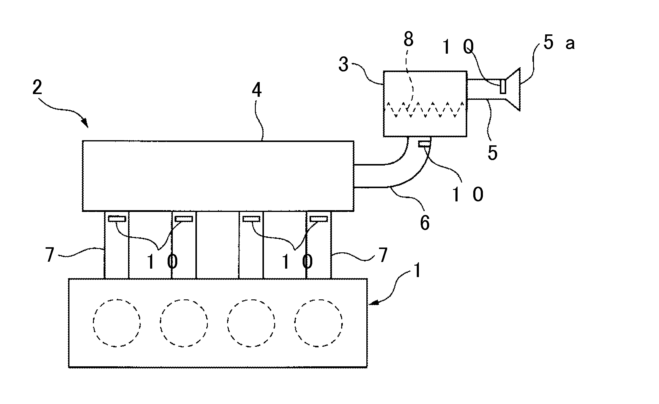
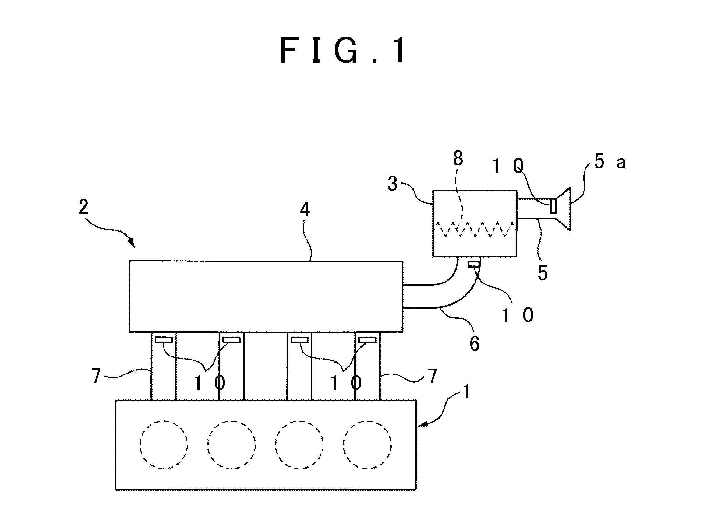
[0039]FIG. 1 schematically illustrates an intake device of a vehicle. Referring now to FIG. 1, a reference sign 1 indicates an engine, and a reference sign 2 indicates an intake device. As illustrated in FIG. 1, the intake device 2 is constituted by an air cleaner 3, a surge tank 4, an intake air introduction pipe 5 to the air cleaner 3, an intake air duct 6 extending toward the surge tank 4 from the air cleaner 3, and intake air branch pipes 7 extending toward the engine 1 from the surge tank 4. Note that a broken line 8 in FIG. 1 indicates an air filter. Intake air flows from an intake air introduction port 5a of the intake air introduction pipe 5 into the air cleaner 3 via the intake air introduction pipe 5, and then, the intake air flows into the intake air duct 6 through the air filter 8. Subsequently, the intake air flows into the surge tank 4 from the intake air duct 6, and then supplied to the engine 1 via the intake air branch pipes 7.

[0040]In the intake device 2 illustrate...


PUM

PropertyMeasurementUnit
Timeaaaaaaaaaa
Shapeaaaaaaaaaa
Electrical conductoraaaaaaaaaa

Abstract

An intake device for a vehicle, in which an intake passage wall surface defining an intake passage is charged with positive charges, includes: a self-discharge static eliminator that is provided on the intake passage wall surface and that decreases an electrification charge amount on that part of the intake passage wall surface which is within a limited range around a mounting part of the self-discharge static eliminator, by providing the self-discharge static eliminator on the intake passage wall surface.

Description

INCORPORATION BY REFERENCE[0001]The disclosure of Japanese Patent Application No. 2014-211952 filed on Oct. 16, 2014 including the specification, drawings and abstract is incorporated herein by reference in its entirety.BACKGROUND OF THE INVENTION[0002]1. Field of the Invention[0003]The present invention relates to an intake device of a vehicle.[0004]2. Description of Related Art[0005]Japanese Patent Application Publication No. 5-238438 (JP 5-238438 A) describes a vehicle configured such that a discharge device such as a discharge antenna is attached to an engine of a vehicle or a member associated with the engine, so that high-voltage electricity, static electricity, or the like generated from an engine portion or stored in the engine portion is discharged and released outside, so as to improve fuel efficiency accordingly.SUMMARY OF THE INVENTION[0006]JP 5-238438 A describes that the vehicle is charged with static electricity, and the static electricity thus charged to the vehicle ...

Claims


Application Information

Patent Timeline
IPC IPC(8): F02M35/10
CPCF02M35/10321F02M35/10242B60K13/02F02M35/10249F02M35/104H01T19/00H05F3/04F15D1/06
Inventor TANAHASHI, TOSHIOKANEHARA, YOJIYAMADA, KOSHI
Owner TOYOTA JIDOSHA KK
Why Eureka
Try Eureka