Image processing apparatus, image pickup apparatus, and image processing method
a technology of image processing and image pickup, which is applied in the field of image processing apparatus, can solve the problems of distortion correction coefficient, difficult storage, and likely no time to calculate the distortion correction coefficient, and achieve the effect of facilitating the operation of distortion correction
- Summary
- Abstract
- Description
- Claims
- Application Information
AI Technical Summary
Benefits of technology
Problems solved by technology
Method used
Image
Examples
embodiment 1
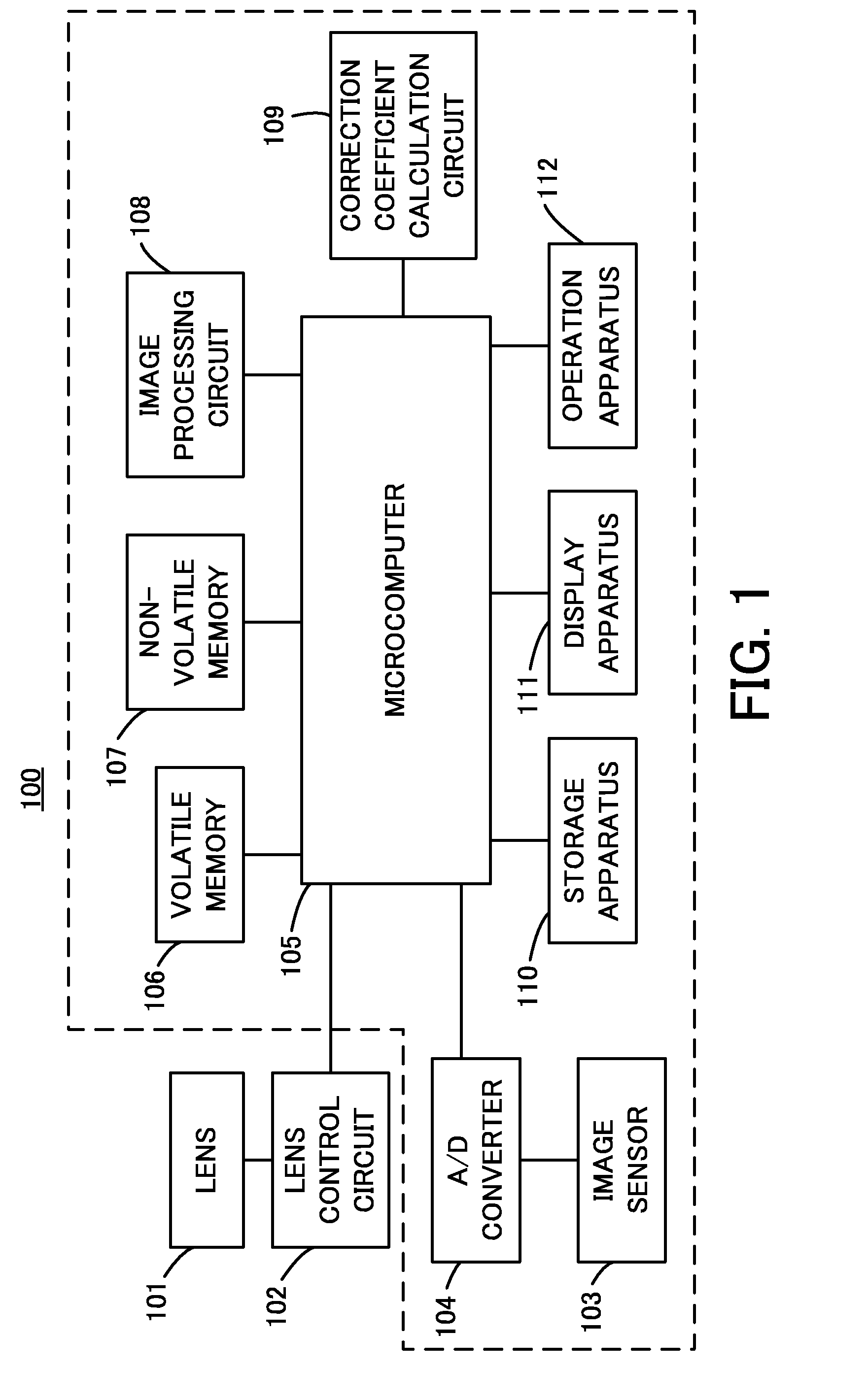
[0031]FIG. 3 is a flowchart of control according to Embodiment 1 of the present invention. At step S301, the microcomputer 105 starts a live view. At step S302, the microcomputer 105 controls the lens control circuit 102 to acquire the lens information such as the zoom position, the zooming direction, the telephoto end, and the wide-angle end of the lens. When it is determined at step S303 that the volatile memory 106 does not store a distortion correction coefficient corresponding to the zoom position of the lens, the microcomputer 105 executes a distortion correction coefficient calculation process illustrated in FIG. 4 using the correction coefficient calculation circuit 109 at step S304. When it is determined at step S303 that the volatile memory 106 stores the distortion correction coefficient, or when the process at step S304 is completed, the microcomputer 105 executes a predicted distortion correction coefficient calculation process illustrated in FIG. 5 using the correction...
embodiment 2
[0040]Embodiment 2 of the present invention performs a predicted distortion correction coefficient calculation control different from that in Embodiment 1. A live view operation is performed in accordance with the flowchart in FIG. 3 similarly to Embodiment 1. This operation is changed to call a predicted distortion correction coefficient calculation process illustrated in FIG. 7 so as to be applicable to a case in which the prediction at step S305 is completed up to the telephoto end or the wide-angle end.
[0041]FIG. 7 is a flowchart of the predicted distortion correction coefficient calculation process with the different predicted distortion correction coefficient calculation control in the case in which the prediction is completed up to the telephoto end and the wide-angle end. The predicted distortion correction coefficient calculation is performed for each of the points spaced at intervals for which the correction coefficient parameters are stored. When it is determined at step ...
embodiment 3
[0046]FIG. 8 is a flowchart of control according to Embodiment 3 of the present invention. First, at step S801, the microcomputer 105 calls a prediction interval calculation process illustrated in FIG. 9 to calculate a calculation interval of predicted distortion correction coefficients. Next at step S802, the microcomputer 105 starts a live view. At step S803, the microcomputer 105 controls the lens control circuit 102 to acquire the lens information such as the zoom position, the zooming direction, the telephoto end, and the wide-angle end of the lens. When it is determined at step S804 that the volatile memory 106 stores a distortion correction coefficient corresponding to the zoom position of the lens, at step S805, the microcomputer 105 executes the distortion correction coefficient acquisition process illustrated in FIG. 6 to acquire the distortion correction coefficient corresponding to the zoom position. When it is determined that the volatile memory 106 does not store the d...
PUM
 Abstract
Description
Claims
Application Information
 - R&D
- Intellectual Property
- Life Sciences
- Materials
- Tech Scout
- Unparalleled Data Quality
- Higher Quality Content
- 60% Fewer Hallucinations
Browse by: Latest US Patents, China's latest patents, Technical Efficacy Thesaurus, Application Domain, Technology Topic, Popular Technical Reports.
© 2025 PatSnap. All rights reserved.Legal|Privacy policy|Modern Slavery Act Transparency Statement|Sitemap|About US| Contact US: help@patsnap.com


