Sound amplifier system and method for amplifying engine sounds

a sound amplifier and engine technology, applied in the direction of machines/engines, combustion air/fuel air treatment, transportation and packaging, etc., can solve the problems of significant attenuation of engine sound within the cabin of the vehicle, the need for audible engine sound within the cabin is not necessarily as desirable, and the system is typically limited to operating within a relatively narrow frequency rang

Active Publication Date: 2016-04-28
MANN HUMMEL GMBH
View PDF0 Cites 6 Cited by
  • Summary
  • Abstract
  • Description
  • Claims
  • Application Information

AI Technical Summary

Benefits of technology

[0006]In one aspect the present disclosure relates to a sound enhancing system, adapted for use with an internal combustion engine of a vehicle, which amplifies engine sounds produced by the engine over a predetermined engine RPM operating range. The sound enhancing system may include a sound enhancing component and a tubular inlet duct. The sound enhancing component may be coupled to structure of the vehicle such that the sound enhancing component is fixed against movement, relative to the engine. The sound enhancing component may be configured to receive air pulsations through the tubular inlet duct, which are being ingested by an induction system of the engine, and where the tubular inlet duct is in communication with a component of the vehicle's induction system. The tubular inlet duct is configured to lengthen and shorten in response to a roll of the engine as the RPM or load of the engine changes. An outlet duct is coupled to an outlet port of the sound enhancing component for channeling sound from the sound enhancing component into or adjacent to a passenger compartment of the vehicle. The change in length of the tubular inlet duct enables a frequency response of the sound enhancing component to be controlled in accordance with the RPM or the load experienced by the engine.
[0007]In another embodiment the present disclosure relates to a sound enhancing system adapted for use with an internal combustion engine of a vehicle to amplify engine sounds produced by the engine over a predetermined engine RPM operating range. The sound enhancing system may include a symposer component and a tubular inlet duct. The symposer component may be coupled to structure of the vehicle such that the symposer component is fixed against movement, relative to the engine. The symposer component is configured to receive air pulsations, from air that is being ingested by an induction system of the engine, through the tubular inlet duct. The tubular inlet duct is in communication with a component of the vehicle's induction system and is configured to lengthen and shorten in response to a roll of the engine as the RPM or load experienced by the engine changes. The tubular inlet duct is also in communication with an inlet port of the symposer component and extends generally perpendicular to a major longitudinal length of the vehicle. The tubular inlet port is configured to change in overall length by at least about 30 mm in response to the roll of the engine. The change in length of the tubular inlet duct, in connection with the symposer component, enables tuning of a frequency response of the symposer component in accordance with changing engine RPM or the load experienced by the engine.
[0008]In still another aspect the present disclosure relates to a method for enhancing a sound of an internal combustion engine of a vehicle, where the sound is produced over a predetermined engine RPM operating range. The method includes affixing a sound enhancing component to structure of the vehicle such that the sound enhancing component is fixed against movement, relative to the engine. A tubular inlet duct is in communication with the sound enhancing component and with a component of an induction system of the engine. The tubular inlet duct is configured to lengthen and shorten in response to a roll of an engine as the RPM or load of the engine changes, and directs ingested air pulsations of the engine into the sound enhancing component. An outlet duct may be used which is in communication with an outlet port of the sound enhancing component. The outlet duct may be used for channeling sound amplified by the sound enhancing component into, or adjacent to, a passenger compartment of the vehicle. A change in length of the tubular inlet duct, which occurs in response to changes in engine RPM or the load experienced by the engine, may be used to help control a frequency response of the sound enhancing component.

Problems solved by technology

With present day vehicle manufacturers placing a heavy emphasis on sound proofing the cabins of their vehicles, this has resulted in significantly attenuating the engine sound within the vehicle's cabin.
Conversely, the need for audible engine sounds within the cabin is not necessarily as desirable while the vehicle is cruising with its engine operating at a relatively low RPM.
However, since the length of the flow duct associated with such a prior developed symposer does not change, and nor does the internal volume within the duct change, such systems are typically limited to operating within a relatively narrow frequency range.
Moreover, such “static” duct constructions are not amenable to being tuned to emphasize or highlight engine sounds at specific, desired frequencies.
As a result, the amplification achieved may not necessarily be achieved over a wide frequency spectrum or a desired frequency spectrum.
Put differently, such prior developed systems may only be able to provide a desired level of amplification of the engine sounds emitted while the engine is operating within a narrow frequency band.
And since the frequency of the emitted sound can change from a lower frequency to a significantly higher frequency as engine RPM increases, this means that a good portion of the frequency spectrum associated with the sounds made by an accelerating engine may not be detected and amplified sufficiently.

Method used


Image

  • Sound amplifier system and method for amplifying engine sounds
  • Sound amplifier system and method for amplifying engine sounds
  • Sound amplifier system and method for amplifying engine sounds

Examples


Embodiment Construction

[0016]The following description is merely exemplary in nature and is not intended to limit the present disclosure, application, or uses. It should be understood that throughout the drawings, corresponding reference numerals indicate like or corresponding parts and features.

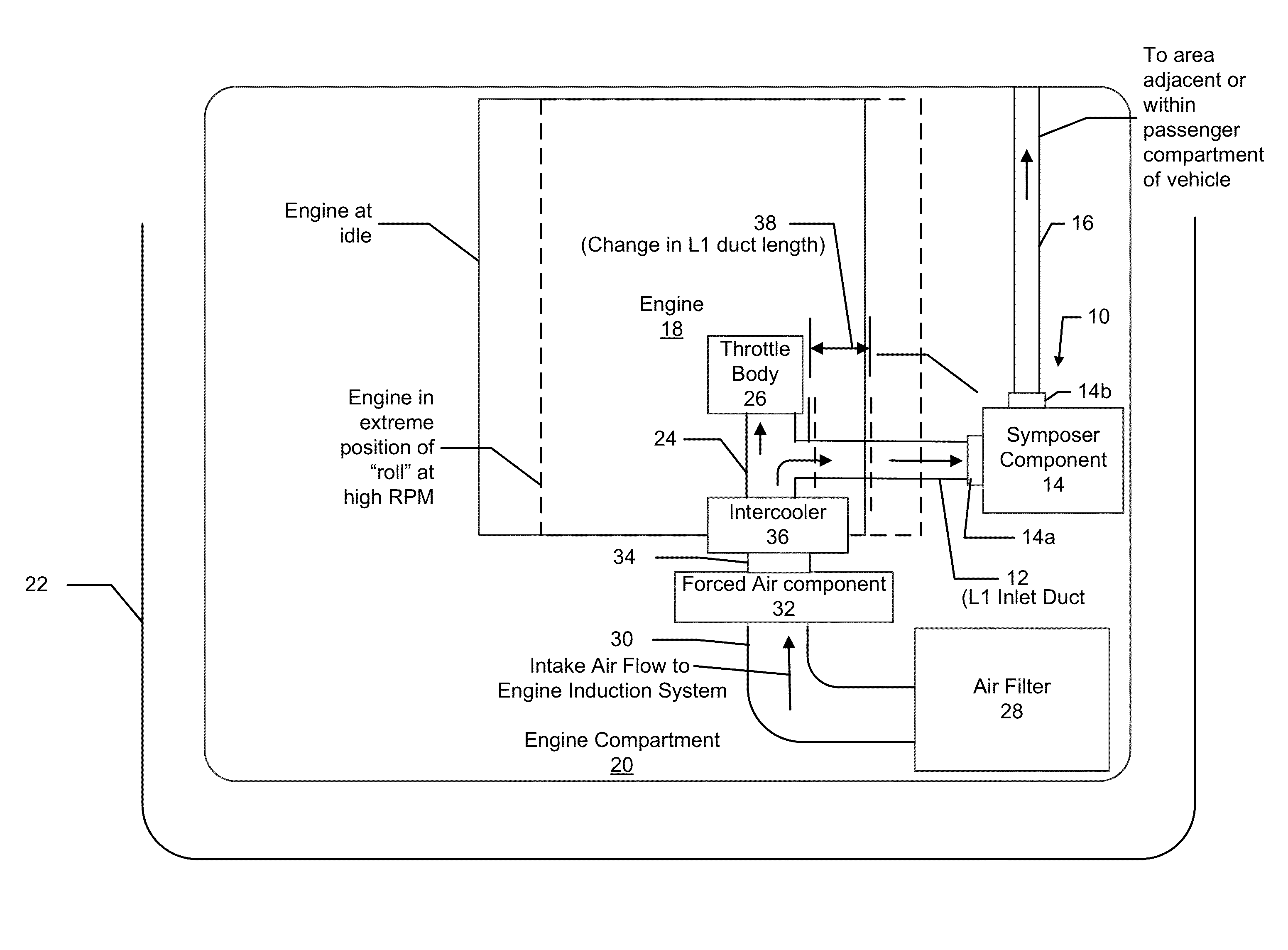
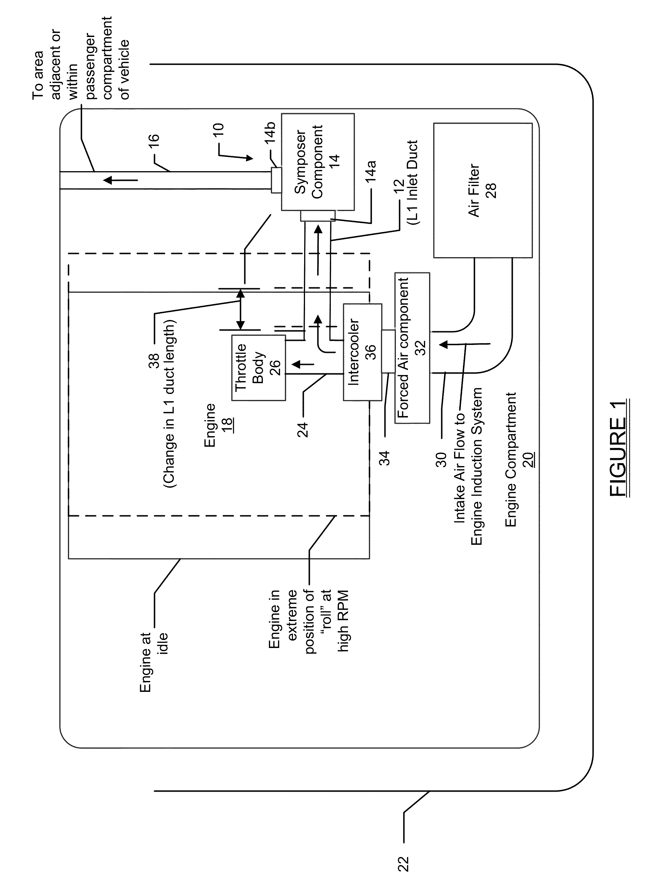
[0017]Referring to FIG. 1 there is shown a sound amplification system 10 in accordance with one embodiment of the present disclosure. The sound amplification system 10 in this example is formed by a symposer system, and simply for discussion purposes will be referred to throughout the following specification as “symposer system 10”. The symposer system 10 will be described in connection with an engine having a forced air induction system, for example a turbocharged or supercharged engine. It will be appreciated, however, that the teachings described herein are equally applicable to naturally aspirated engines which typically use sound pipes. As such, the embodiments of the symposer system 10 described herein are n...


PUM


Abstract

A sound enhancing system is disclosed for use with an engine of a vehicle to amplify engine sounds produced by the engine over a predetermined engine RPM operating range. The sound enhancing system includes a sound enhancing component which may be fixedly mounted within an engine compartment so that it does not move relative to the engine as the engine experiences engine roll during changes in engine RPM or a load experienced by the engine. An inlet duct communicates with an inlet of the sound enhancing component and receives air pulsations drawn in by the vehicle's induction system, and is able to vary in length as the engine roll occurs, when engine RPM increases and decreases. This enables a frequency response of the sound enhancing component to be modified in accordance with changing engine RPM or the load experienced by the engine.

Description

FIELD[0001]The present disclosure relates to devices and systems for amplifying engine sounds, wherein the engine sounds change in volume and frequency in accordance with the engine RPM of a motor vehicle engine, and more particularly to a noise amplification system and method which is able to respond to a broader frequency range of engine sounds associated with varying engine loads and varying engine RPM.BACKGROUND[0002]The statements in this section merely provide background information related to the present disclosure and may not constitute prior art.[0003]Sound amplifying devices for amplifying the sounds emitted from a motor vehicle engine are sometimes referred to as “symposers”. Symposers are used in motor vehicle applications to enhance and / or modify the sound produced by a vehicle engine as the engine is operating. With present day vehicle manufacturers placing a heavy emphasis on sound proofing the cabins of their vehicles, this has resulted in significantly attenuating t...

Claims


Application Information

Patent Timeline
Patent Type & Authority Applications(United States)
IPC IPC(8): H03G3/20B60Q5/00
CPCB60Q5/005H03G3/20F02M35/1294
Inventor MAH, KEAT BOON
Owner MANN HUMMEL GMBH
Why Eureka
Try Eureka