Apparatus for controlling light module

a technology for controlling apparatuses and light modules, applied in the direction of electric variable regulation, process and machine control, instruments, etc., can solve the problem that control signals do not comprise sufficient power to power loads

Active Publication Date: 2016-04-28
SIGNIFY HLDG BV
View PDF3 Cites 45 Cited by
  • Summary
  • Abstract
  • Description
  • Claims
  • Application Information

AI Technical Summary

Benefits of technology

[0032]One signal for controlling as well as powering a lamp makes it relatively complicated to increase a number of control options. A basic idea is that a control of a light module is to be sep...

Problems solved by technology

Control signals do not comprise suff...

Method used


Image

  • Apparatus for controlling light module
  • Apparatus for controlling light module
  • Apparatus for controlling light module

Examples


Embodiment Construction

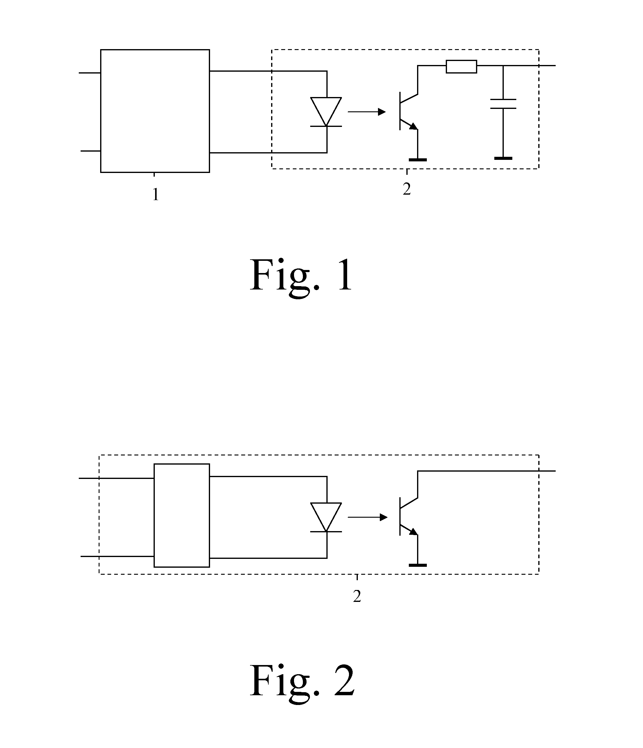
[0043]In the FIG. 1, an embodiment of first and second circuits 1, 2 is shown. The first circuit 1 comprises for example a phase-cut detector for detecting a phase-cut of a first signal coming from a classical dimmer such as for example a triac dimmer and for providing a pulse width modulation signal. A pulse width of the pulse width modulation signal depends on and may for example be proportional with the detected phase-cut. The second circuit 2 for example comprises an isolator such as for example an opto-coupler followed by a filter such as for example a RC filter having a smoothing function that converts the pulse width modulation signal into a DC voltage signal. An amplitude of the DC voltage signal depends on and may for example be proportional with the pulse width.

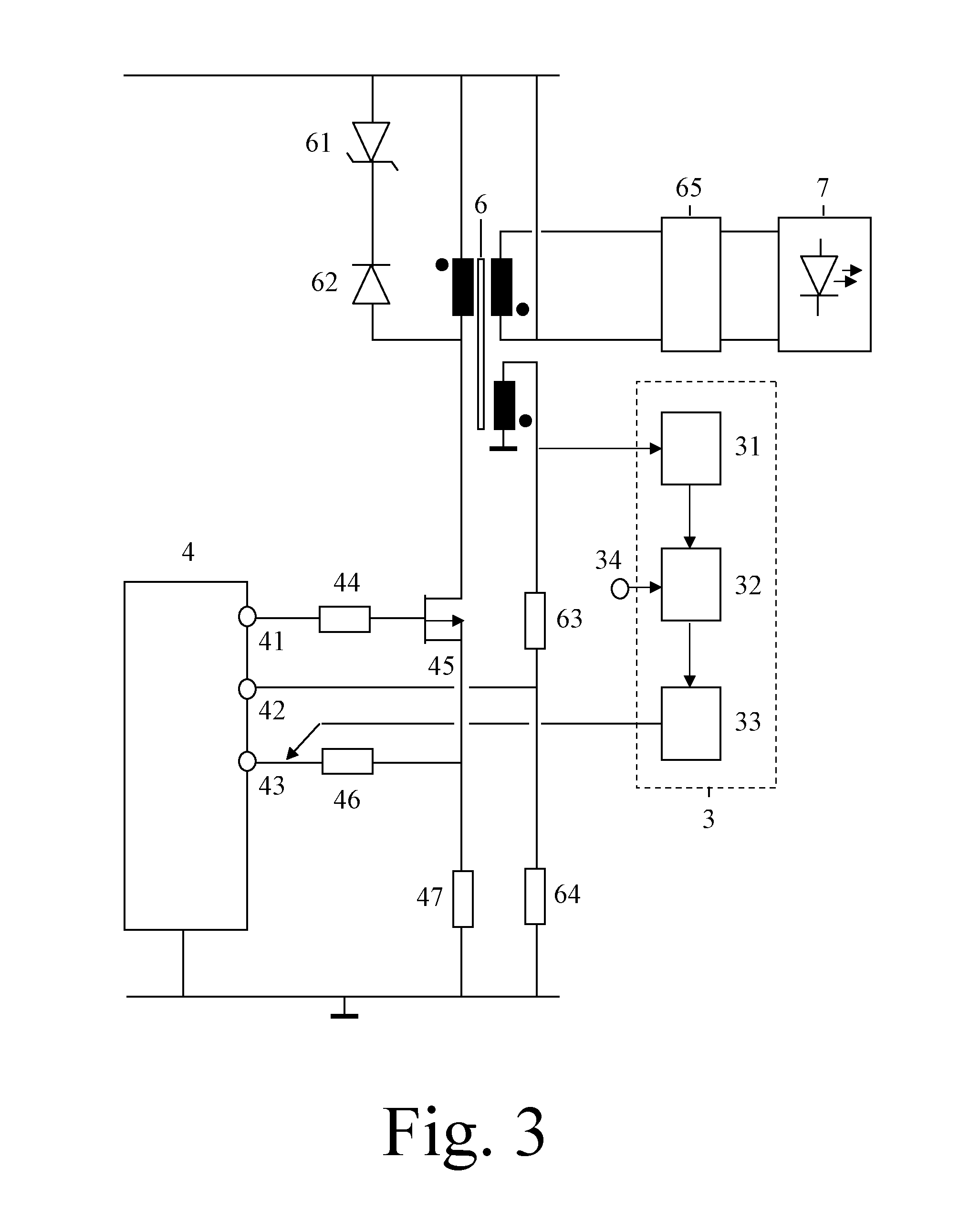
[0044]Alternatively, the first circuit 1 may for example be realized via a fourth circuit as discussed for the FIG. 3 or may for example be realized as shown in the FIG. 7.

[0045]In the FIG. 2, an embodiment of a sec...


PUM


Abstract

Apparatuses for controlling light modules (5) comprise first circuits (1) for detecting first control information transported via first signals and second circuits (2) for converting first control information into second control information. The second control information is transported via second signals. The first and second control information define light settings of the light modules (5) and have different representations. The first control information may be phase-cut information or first data. The second control information may be a parameter of the second signal or second data. The apparatus may further comprise a third circuit (3) for converting power from the first signals into third signals destined for power inputs (51) of the light modules (5). The second signals may be destined for control inputs (52) of the light modules (5). This way, a control of a light module (5) has been separated from powering the light module (5). Many more control options have become possible.

Description

FIELD OF THE INVENTION[0001]The invention relates to an apparatus for controlling a light module. The invention further relates to a light module. Examples of such a light module are light modules comprising light emitting diode circuits.BACKGROUND OF THE INVENTION[0002]US 2012 / 0262084 A1 discloses a constant voltage dimmable LED driver.SUMMARY OF THE INVENTION[0003]It is an object of the invention to provide an apparatus for controlling a light module. It is a further object of the invention to provide a light module.[0004]According to a first aspect, an apparatus for controlling a light module is provided, the apparatus comprising[0005]a first circuit for detecting first control information, the first control information being transported via a first signal, and[0006]a second circuit for converting the first control information into second control information, the first and second control information defining light settings of the light module, a representation of the second contr...

Claims


Application Information

Patent Timeline
IPC IPC(8): H05B33/08H05B44/00
CPCH05B33/0815H05B33/0851H05B39/08H05B45/10H05B45/31H05B45/385H05B44/00
Inventor LINNARTZ, JOHAN-PAUL MARIE GERARDABBO, ANTENEH ALEMUQIU, YIFENG
Owner SIGNIFY HLDG BV
Why Eureka
Try Eureka