Bottle jack

a jack and jack body technology, applied in the field of jacks, can solve the problems of levers being lost, damage to the object held by the jack, etc., and achieve the effect of optimizing the space required for storing the jack

Inactive Publication Date: 2016-05-05
MELCHOR GABILONDO
View PDF9 Cites 4 Cited by
  • Summary
  • Abstract
  • Description
  • Claims
  • Application Information

AI Technical Summary

Benefits of technology

[0020]According to another preferred embodiment of the invention, the bottle jack comprises a main body and a shaft capable of being moved with respect to the main body in a direction of expansion and in a direction of compression for lifting and lowering a load, respectively. To cause movement of the shaft, the jack comprises a hydraulically operated system which is capable of providing pressure to an inner hydraulic fluid, said pressure finally acting on the shaft to cause movement thereof in the direction of expansion. The jack is further provided with a lever assembly which can be lowered by a user to operate the hydraulically operated system, i.e., to cause an increase in hydraulic fluid pressure. The jack according to one embodiment of the invention furthermore has the particularity that the lever assembly is telescopic and the total length of the lever assembly is variable. Having a telescopic lever assembly the length of which is variable allows the lever assembly to adopt different lengths depending on usage needs. Furthermore, it facilitates being able to stow away the lever assembly to a position of minimal length when the jack is to be stored, optimizing the space required for storing the jack.
[0021]In another preferred embodiment, the bottle jack comprises a receiving opening in which a hook-type element comprised in the lever assembly can be engaged. This allows the telescopically stowed lever assembly to be stored hanging from the main body and therefore together with it, the jack being stored as a single integral unit. The risk of the lever assembly getting lost when the jack is not being used is therefore reduced or eliminated in its entirety.

Problems solved by technology

The jack must assure that the object is lowered in a controlled manner without causing the object to lose balance, fall or overturn, all of which are extremely dangerous for the jack user and which can cause damage to the object held by the jack.
One drawback of this way of storing the jack is that the lever tends to get lost.

Method used


Image

  • Bottle jack
  • Bottle jack
  • Bottle jack

Examples


Embodiment Construction

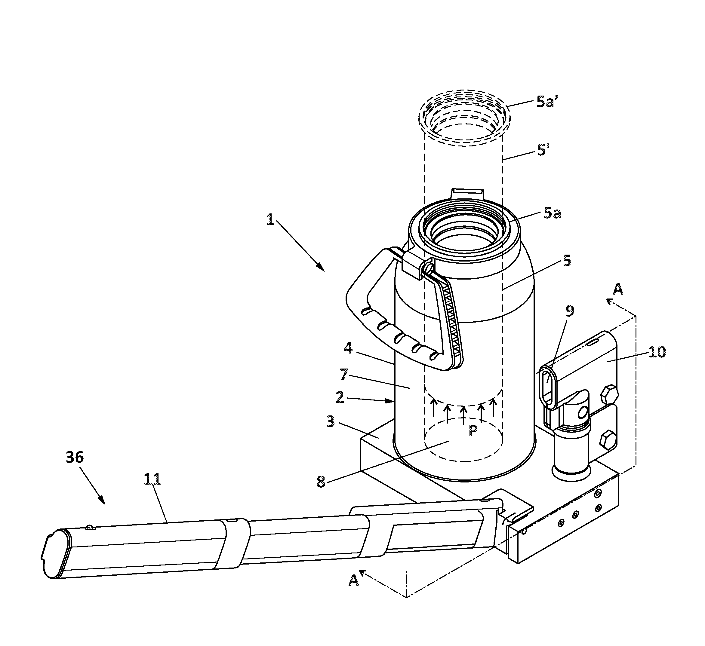
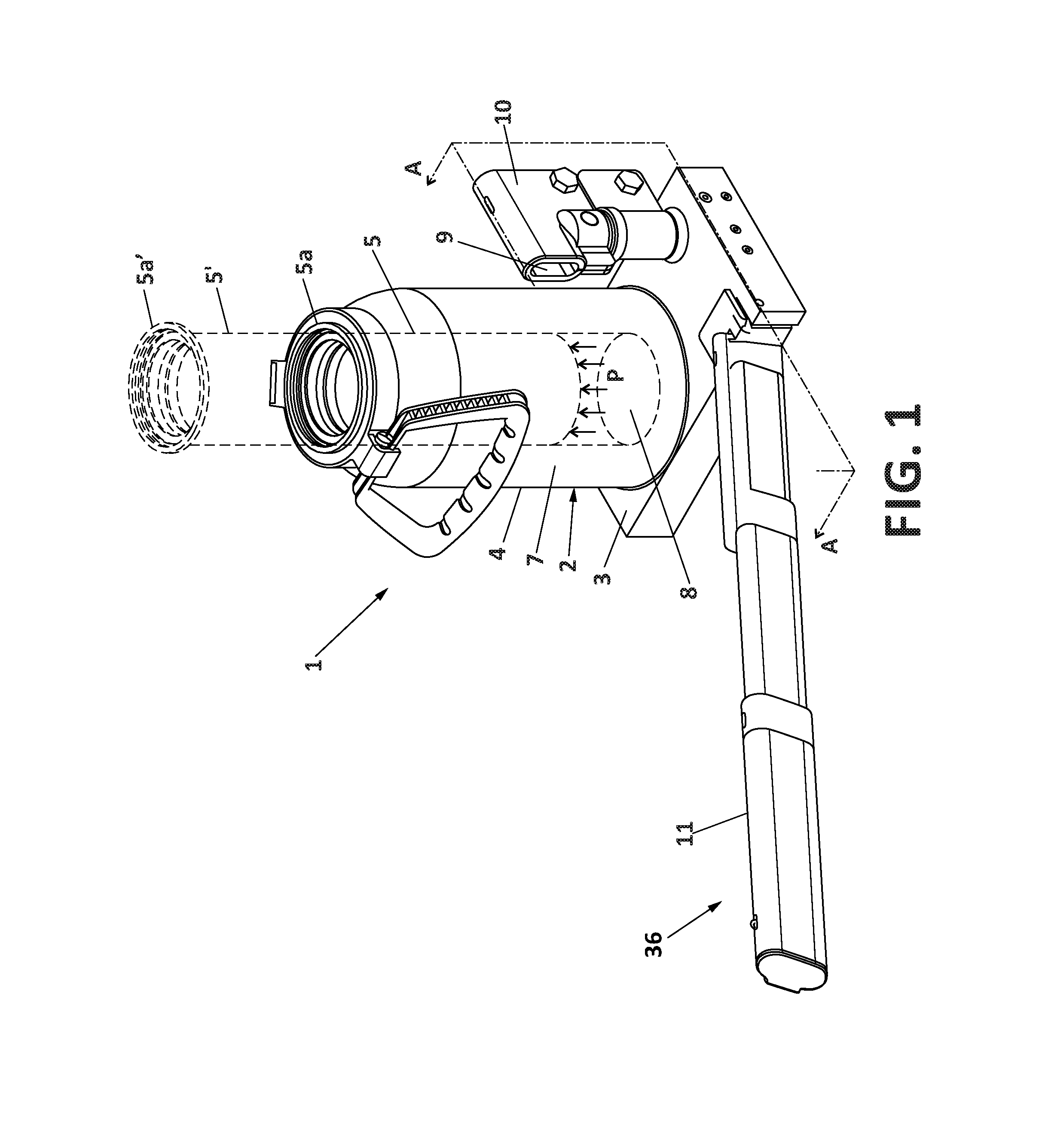
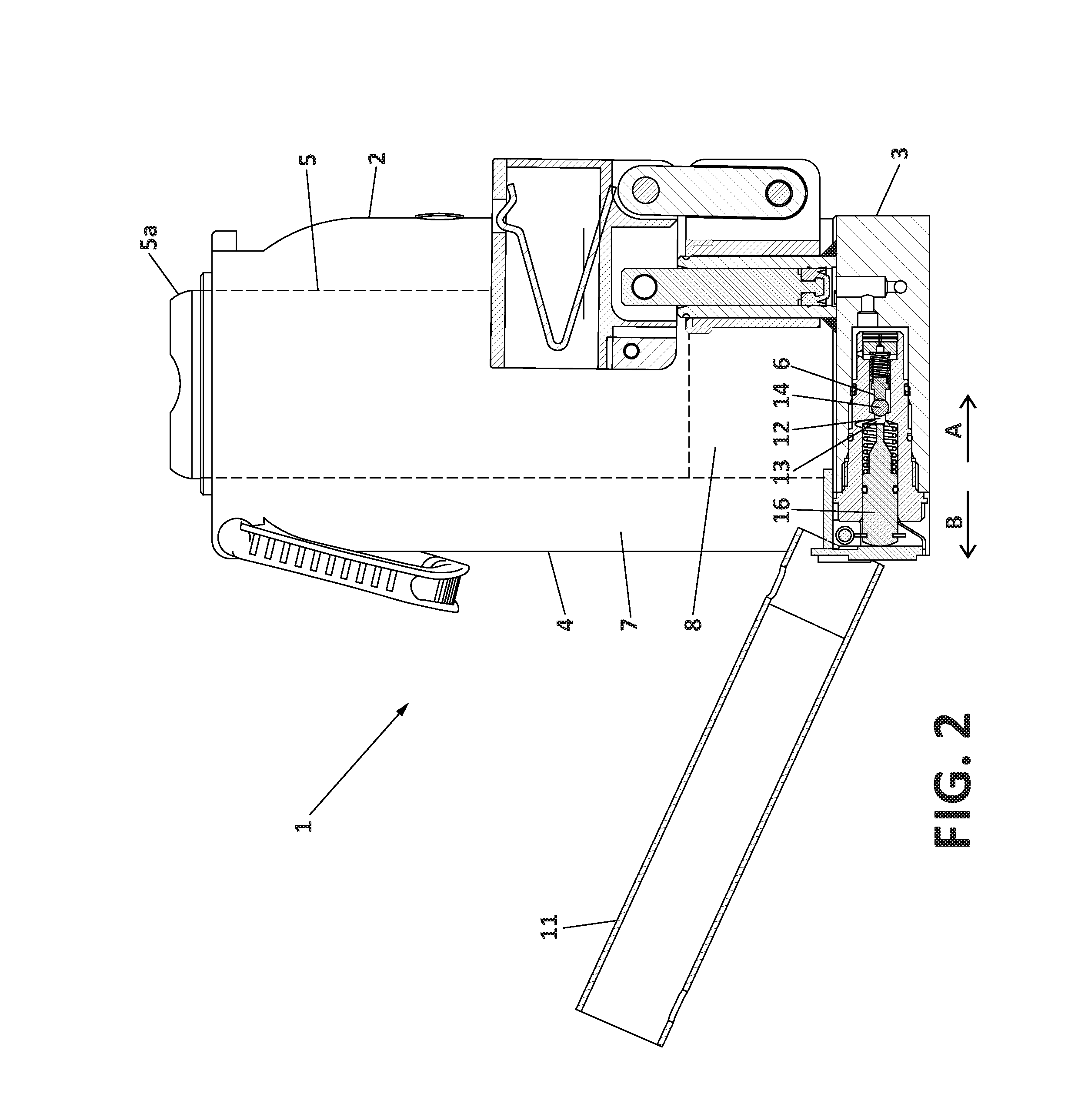
[0033]FIG. 1 shows a first embodiment of a bottle jack according to the invention. The jack (1) comprises a main body (2) which, in the present embodiment, is formed by a base (3) intended for being supported on the ground or other applicable surface, and a bottle (4) which rises above the base (3). The jack (1) further comprises a shaft (5) expanding or contracting with respect to the main body (2), in this case with respect to the bottle (4), for lifting and lowering the load. The shaft (5) has an upper portion (5a) intended for contacting the load and pushing it. In FIG. 1, the shaft (5) is retracted inside the bottle (4). Nevertheless, to illustrate movement of the shaft (5), the shaft (5) and the upper portion (5a) are further depicted with dotted lines in an imaginary extended position (5′, 5a′) in which both have been expanded with respect to the bottle (4) due to pressure exerted on the shaft (5) by a hydraulic fluid contained in a hydraulically operated circuit (6). The hyd...


PUM


Abstract

The present invention relates to a bottle jack comprising a main body and a shaft that expands or contracts, further comprising:
    • a passage space communicating a hydraulically operated circuit with an unloading circuit through which the controlled outlet of hydraulic fluid from the hydraulically operated circuit and subsequent lowering of the shaft occur;
    • a closure element elastically pushed towards the passage space to prevent the outlet of hydraulic fluid therethrough;
    • a ram assembly elastically pushed in the longitudinal backward movement direction (B) with a force greater than the force with which the closure element is elastically pushed against the passage space; and
    • a telescopic lever assembly which can be lowered by a user to operate the hydraulically operated system.

Description

FIELD OF THE ART[0001]The invention relates to a bottle jack of the type formed by a main body and a hydraulically operated shaft expanding or contracting with respect to the main body for lifting and lowering a load.STATE OF THE ART[0002]A bottle jack is an apparatus which allows lifting very heavy objects and is basically formed by a generally cylindrical main body with a hydraulically operated shaft projecting from the inside thereof. The shaft is capable of moving up and down when hydraulic operation is activated by a user, which allows lifting or lowering a heavy object. The name “bottle” comes from the fact that a significant portion of the main body usually has a shape resembling a bottle.[0003]To allow lifting the heavy object, the bottle jack comprises an operating mechanism on which the user can act. Said operating mechanism is generally a lever connected in an articulated manner to the rest of the jack. When the user pushes the lever and causes rotation thereof with respe...

Claims


Application Information

Patent Timeline
Patent Type & Authority Applications(United States)
IPC IPC(8): B66F3/42B66F3/25
CPCB66F3/25B66F3/42
Inventor MARTINEZ MARTINEZ, ANTONIO
Owner MELCHOR GABILONDO
Why Eureka
Try Eureka