Steel bar layer at external corner

A reinforcement layer and position technology, applied in the direction of structural elements, building components, building reinforcements, etc., can solve the problems of steel protection layer not meeting the requirements, thick plate thickness, small plate thickness, etc., to reduce the number of overlapping layers of steel bars, The effect of fewer layers and reduced plate thickness

Pending Publication Date: 2020-01-24
ELITE ARCHITECTURAL CO LTD
View PDF0 Cites 0 Cited by
  • Summary
  • Abstract
  • Description
  • Claims
  • Application Information

AI Technical Summary

Problems solved by technology

Due to the large number of overlapping layers of steel bars, the design tends to ignore the space requirements of the steel bar layout or not to optimize the space requirements. Often, the design plate thickness is too small to meet the requirements, or the design plate thickness meets the requirements, but the plate thickness is too large. Thick, resulting in waste, the actual situation is the vast majority of the former
The construction is often exposed according to the conventional reinforcement arrangement and design slab thickness pouring, and the reinforcement protection layer does not meet the requirements

Method used


Image

  • Steel bar layer at external corner
  • Steel bar layer at external corner
  • Steel bar layer at external corner

Examples


Embodiment Construction

[0028] The following will clearly and completely describe the technical solutions in the embodiments of the present invention with reference to the accompanying drawings in the embodiments of the present invention. Obviously, the described embodiments are only some, not all, embodiments of the present invention. Based on the embodiments of the present invention, all other embodiments obtained by persons of ordinary skill in the art without creative efforts fall within the protection scope of the present invention.

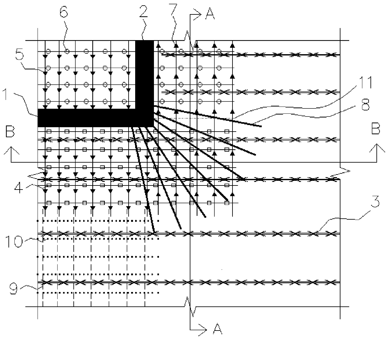
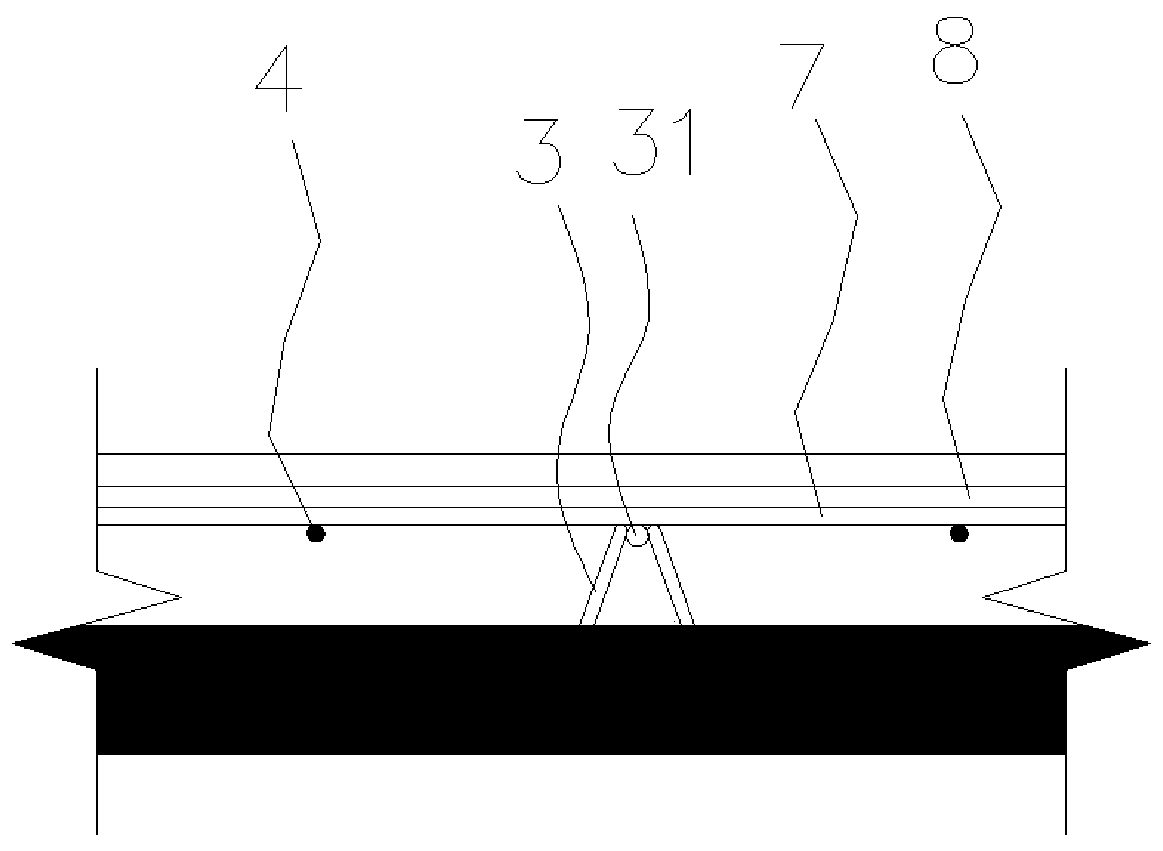
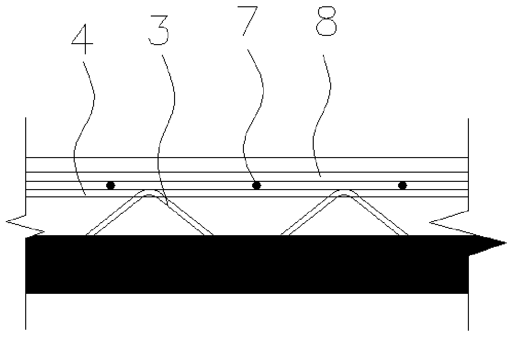
[0029] see Figure 1 to Figure 3 Shown, the preferred embodiment of the present invention, a kind of reinforcing bar layer that is positioned at the male corner position, the first wall body 1 and the second wall body 2 that are perpendicular to each other are arranged at the male corner position, the reinforcing bar layer that is positioned at the male corner position includes multiple Group truss tendons 3, multiple first upper iron stress tendons 4, multiple sec...


PUM


Abstract

The invention relates to the technical field of building engineering, and discloses a steel bar layer at an external corner. A first wall body and a second wall body which are perpendicular to each other are arranged at the external corner, and the steel bar layer at the external corner comprises a plurality of sets of truss bars, a plurality of first upper iron carrying bars, a plurality of second upper iron carrying bars, a plurality of third upper iron carrying bars, a plurality of first upper iron distribution bars and a plurality of radial carrying bars; the multiple first upper iron carrying bars are all parallel to the first wall body and are arranged on the outer side of the first wall body at intervals; the multiple first upper iron distribution bars are all located above the truss bars and are perpendicular to the first wall body; the multiple first upper iron distribution bars are all arranged on the outer side of the second wall body at intervals; and the multiple radial carrying bars are all located above the first upper iron distribution bars and evenly arranged in a radiation ray shape from the external corner. By adopting the steel bar layer at the external corner,the advantages that the arranging mode and the structure are reasonable, the number of steel bar layers is small, super-thick pouring of composite slabs can be avoided, the cost is saved, and the spatial demand is optimized are achieved.

Description

technical field [0001] The invention relates to the technical field of construction engineering, in particular to a reinforcement layer located at an external corner. Background technique [0002] In the prior art, it is usually necessary to add radial ribs at the external corners at the external corners of the special-shaped laminated slabs. The radial ribs at the external corners and the radial distribution ribs in this position are two layers of steel bars. The iron stress ribs and distribution ribs on the top surface of the floor slab are 2 layers of steel bars, a total of 4 layers. Considering that there is a layer of steel bars on the upper chord of the truss bars, there are actually at most 5 layers of steel bars overlapping. Due to the large number of overlapping layers of steel bars, the design tends to ignore the space requirements of the steel bar layout or not to optimize the space requirements. Often, the design plate thickness is too small to meet the requirem...

Claims


Application Information

Patent Timeline
Patent Type & Authority Applications(China)
IPC IPC(8): E04C5/06E04B5/36
CPCE04B5/36E04C5/06E04C5/064
Inventor 张艾荣许文杰陈敬恒邓宝瑜黎加纯李一品
Owner ELITE ARCHITECTURAL CO LTD
Why Eureka
Try Eureka