Solar thermal power generation equipment

A technology of thermal power generation and solar energy, which is applied in the direction of solar thermal energy, solar collectors, solar heating systems, etc., and can solve problems such as large construction expenses

Active Publication Date: 2016-11-16
索拉莱特聚光太阳能发电技术有限责任公司
View PDF6 Cites 0 Cited by
  • Summary
  • Abstract
  • Description
  • Claims
  • Application Information

AI Technical Summary

Problems solved by technology

This would result in substantial construction expenditures

Method used


Image

  • Solar thermal power generation equipment

Examples


Embodiment Construction

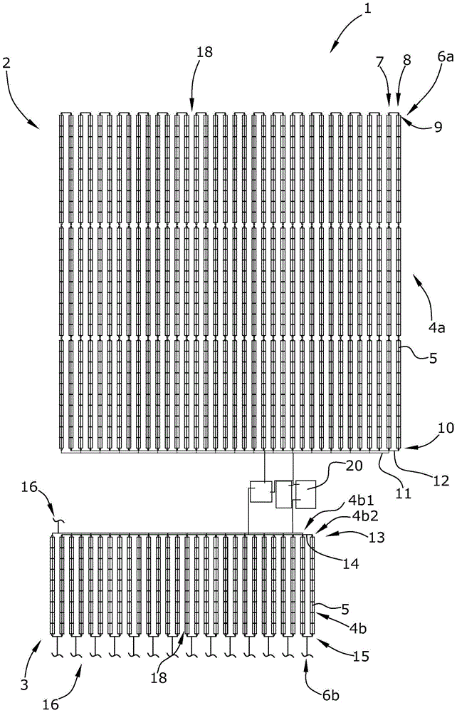
[0025] The solar thermal power plant 1 is composed of an evaporator 2 and a superheater 3 .

[0026] The evaporator 2 is formed by a first number of parabolic trough collectors 4 and the superheater 3 is formed by a second number of parabolic trough collectors 4 .

[0027] Each parabolic trough collector 4 consists of several parabolic trough segments 5 . In this configuration, the parabolic trough collectors 4 a of the evaporator 2 are each formed from ten parabolic trough segments 5 , while the parabolic trough collectors 4 b of the superheater 3 are each formed from nine parabolic trough segments 5 .

[0028] The parabolic trough collectors 4a, 4b are arranged in several annular structures 6a, 6b connected in parallel. In this arrangement, the annular structure 6a of the evaporator 2 is formed by six parabolic trough collectors 4a in each case. The annular structure 6b of the superheater 3 is formed in each case by two parabolic trough collectors 4b.

[0029] The annular...


PUM


Abstract

The invention relates to a solar-thermal power plant (1) having direct vaporization of a thermal carrier having parabolic channel collectors (4a, 4b), each consisting of a plurality of parabolic channel segments (5), wherein thermal energy of the sunlight can be supplied to the thermal carrier via the parabolic channel collectors (4a, 4b), and having at least one vapor turbine (20) which can be driven by the vaporized thermal carrier, wherein the parabolic channel collectors (4a, 4b) are arranged in a plurality of loops (6a, 6b), wherein the loops (6a, 6b) are connected parallel so that a first number of parabolic channel collectors (4a) form a vaporizer (2) and a second number of parabolic channel collectors (4b) form a superheater (3).

Description

technical field [0001] The invention relates to a solar thermal power generation device which uses a heat carrier to directly evaporate. Background technique [0002] Solar thermal power plants exist in a variety of ways. In addition to solar tower power plants and Fresnel collector plants, there are also parabolic trough power plants, which reflect sunlight via parabolic trough-shaped reflectors to tubular absorbers through which the heat-carrying medium passes . Several such parabolic trough shaped reflectors, also called parabolic trough segments, combine to form a parabolic trough collector. [0003] Parabolic trough power plants are commonly used to generate steam to operate steam turbines using conventional water steam circuits. Usually, in this respect, two different structural designs are used. In a common type of system, the oil is heated through a parabolic trough collector, where the oil transfers thermal energy to the water vapor circuit via a heat exchanger....

Claims


Application Information

Patent Timeline
Patent Type & Authority Patents(China)
IPC IPC(8): F22B1/00F22B29/08F24S23/74
CPCF22B1/006F22B29/08
Inventor 约阿希姆·克鲁格
Owner 索拉莱特聚光太阳能发电技术有限责任公司
Why Eureka
Try Eureka