Sealing device

Active Publication Date: 2016-05-05
HANWHA POWER SYST CO LTD
View PDF3 Cites 1 Cited by
  • Summary
  • Abstract
  • Description
  • Claims
  • Application Information

AI Technical Summary

Benefits of technology

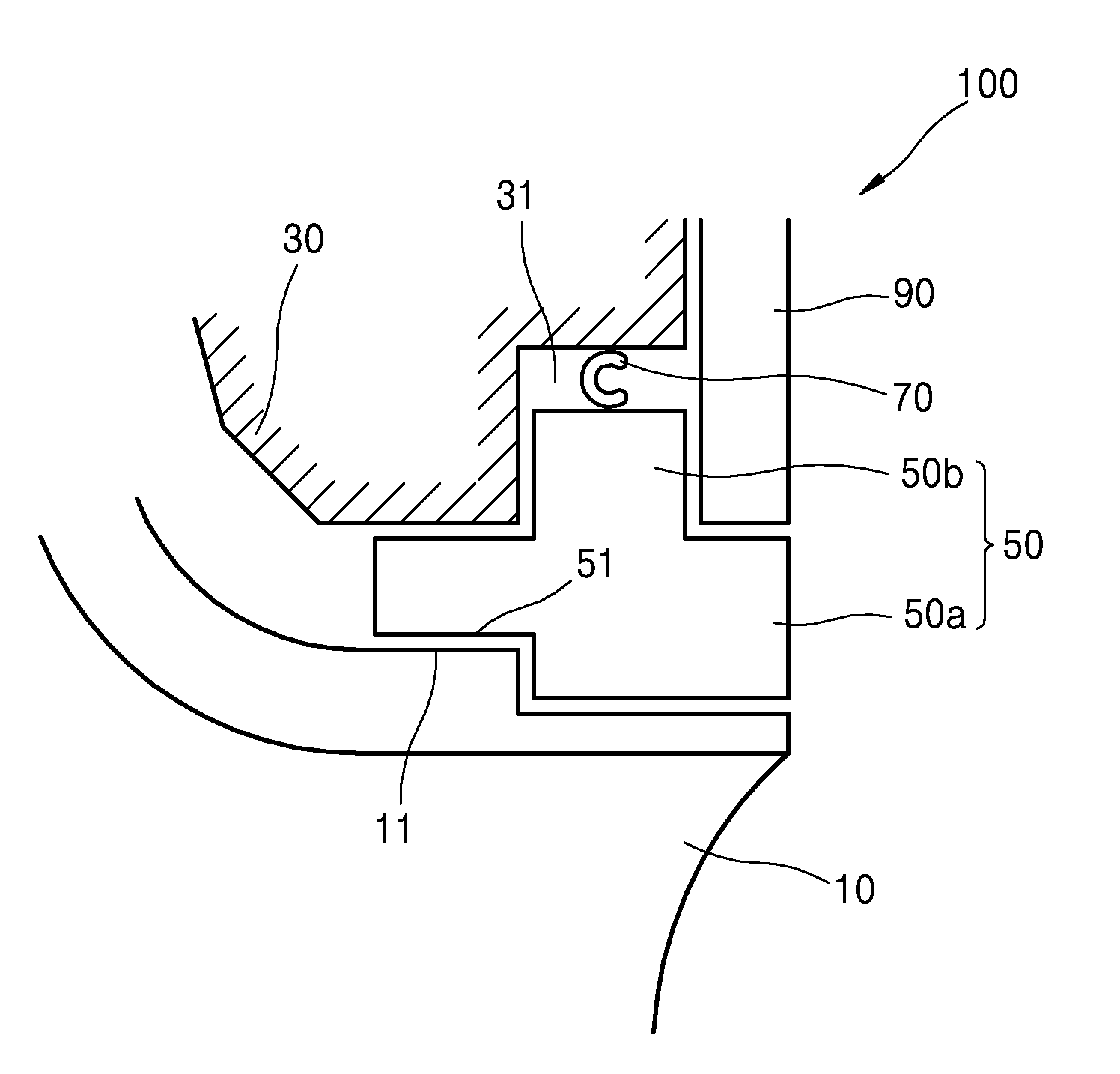
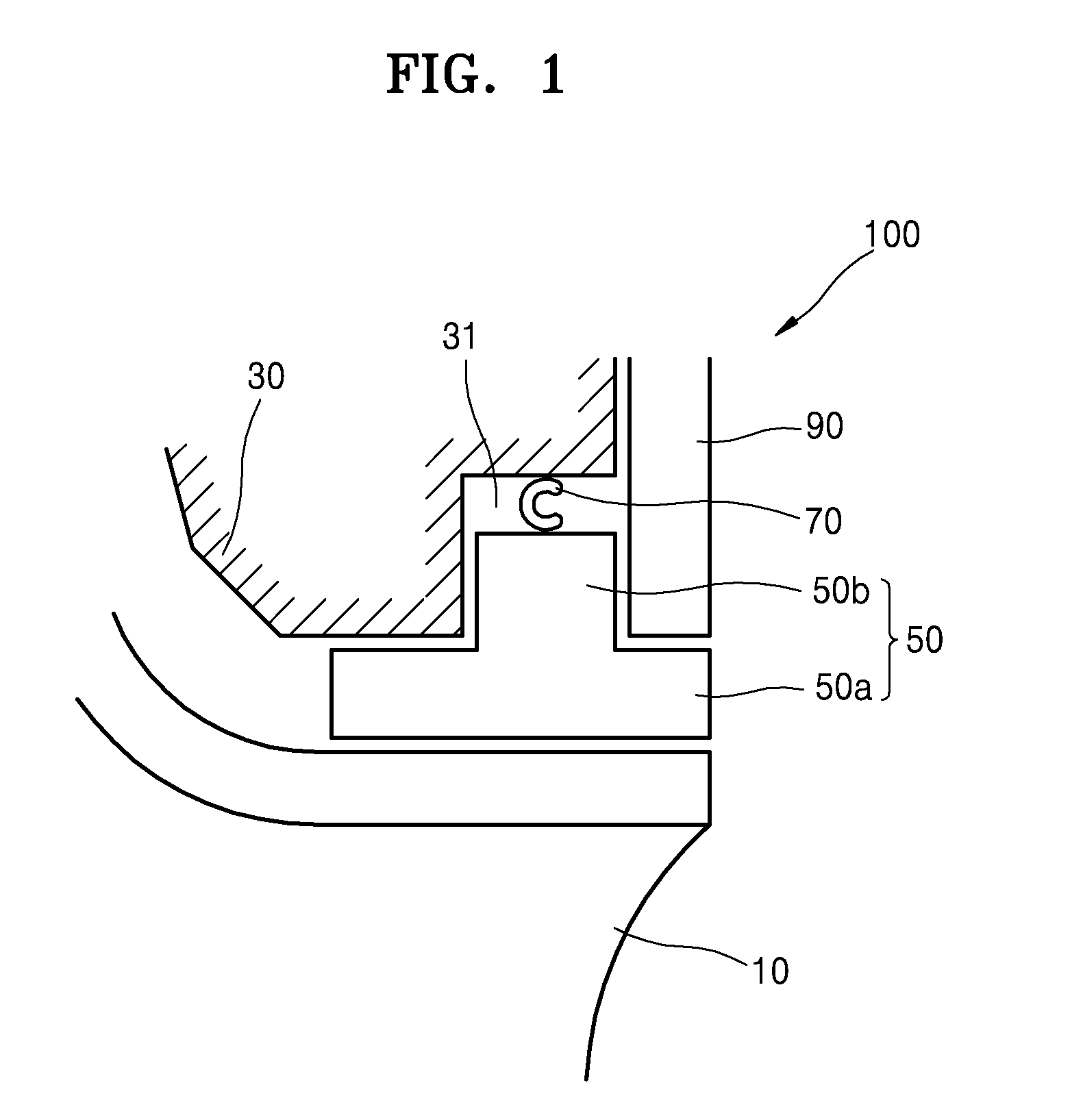
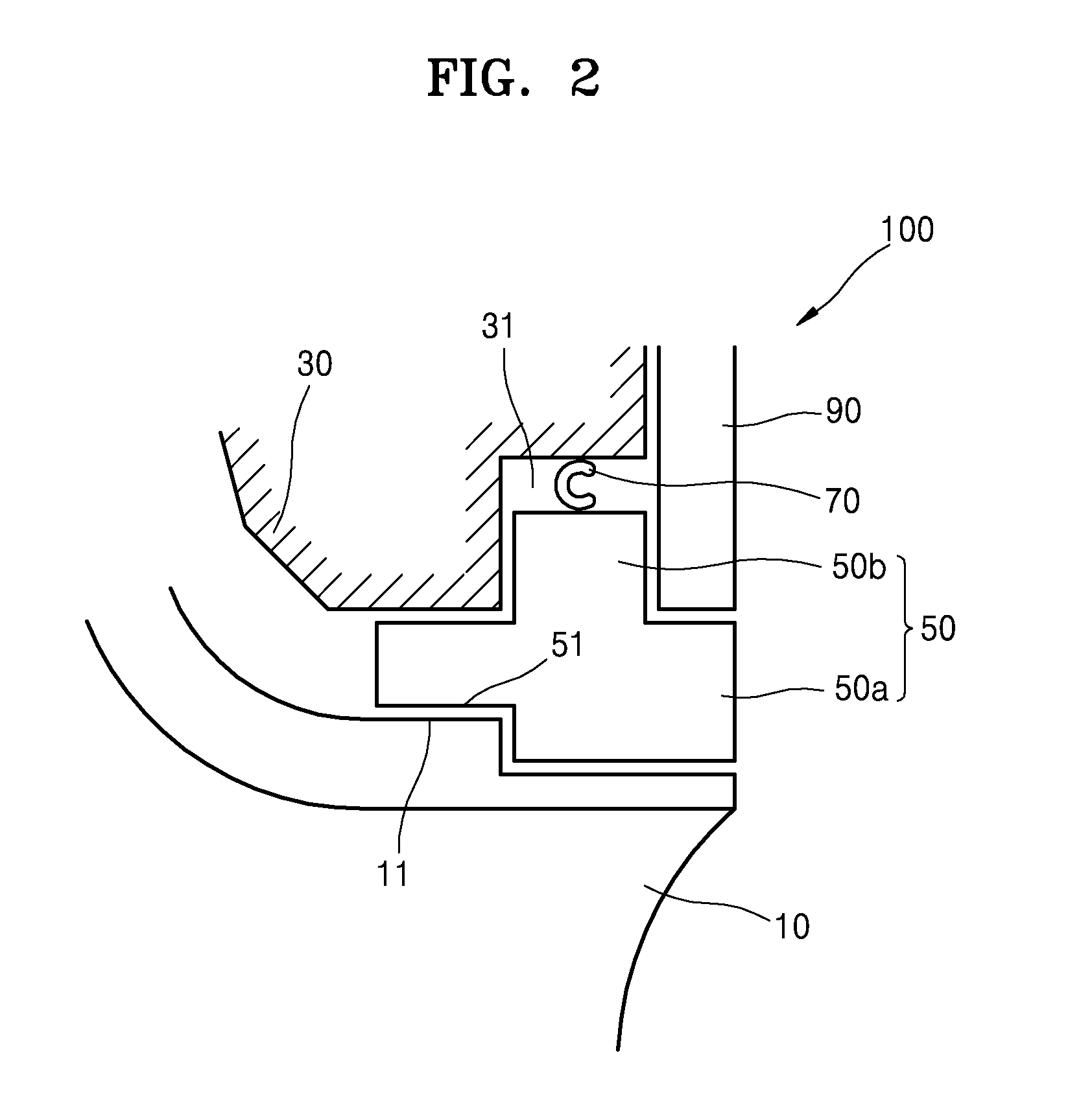
The patent describes a sealing device that includes an impeller, a casing with a groove portion, a floating ring, and a centering ring. The centering ring is elastically deformed when pressed by the floating ring against the casing. It can be made of elastic material and has a "C" or "O"-shaped cross-section. The device also includes a retaining ring that contacts the surface of the floating ring. The impeller may have a step surface, and the floating ring may have a step portion with a corresponding shape to the step surface in a surface facing the impeller. In some embodiments, the floating ring may have a protruding portion that protrudes from a base portion and contacts the impeller. The centering ring is configured to contact the casing and the floating ring. The technical effect of this sealing device is to provide an improved sealing performance in a cost-effective and easy-to-use manner.

Problems solved by technology

In this regard, abrasion occurs between the impeller and a casing due to the rotation of the impeller, and the fluid may escape to the outside during a process of mixing the fluid and the efficiency of the impeller may be negatively impacted.

Method used


Image

  • Sealing device
  • Sealing device
  • Sealing device

Examples


Embodiment Construction

[0021]As the current inventive concept allows for various changes and numerous exemplary embodiments, particular exemplary embodiments will be illustrated in the drawings and described in detail in the written description. However, this is not intended to limit the inventive concept to particular modes of practice, and it is to be appreciated that all changes, equivalents, and substitutes that do not depart from the spirit and technical scope of the inventive concept are encompassed. Although different exemplary embodiments are illustrated for description of the present invention, like reference numerals in the drawings denote like elements

[0022]While such terms as “first”, “second”, etc., may be used to describe various components, such components must not be limited to the above terms. The above terms are used only to distinguish one component from another.

[0023]The terms used in the present specification are merely used to describe particular embodiments, and are not intended to ...


PUM


Abstract

Provided is a sealing device including: an impeller configured to rotate; a casing including a groove portion in a surface facing the impeller; a floating ring configured to float between the casing and the impeller and configured to be inserted into the groove portion; and a centering ring provided inside the groove portion and provided between the casing and the floating ring.

Description

BACKGROUND[0001]1. Field[0002]Apparatuses consistent with exemplary embodiments relate to a sealing device, and more particularly, to a sealing device for keeping a fluid from leaking out of an impeller that rotates the fluid in a compressor.[0003]2. Description of the Related Art[0004]To increase pressure of a fluid, the fluid may be accelerated outward by rotating an impeller thereby accelerating the fluid outwards from the center of rotation.[0005]In this regard, abrasion occurs between the impeller and a casing due to the rotation of the impeller, and the fluid may escape to the outside during a process of mixing the fluid and the efficiency of the impeller may be negatively impacted.SUMMARY[0006]One or more exemplary embodiments include a sealing device.[0007]Additional aspects will be set forth in part in the description which follows and, in part, will be apparent from the description, or may be learned by practice of the presented exemplary embodiments.[0008]According to an ...

Claims


Application Information

Patent Timeline
IPC IPC(8): F04D29/08F04D29/52F04D29/42F04D29/28F04D29/32
CPCF04D29/083F04D29/284F04D29/522F04D29/4206F04D29/321F01D11/025F01D11/08F04D29/162F04D29/164F04D29/526F05D2240/307F05D2250/182
Inventor WYGANT, KARL D.
Owner HANWHA POWER SYST CO LTD
Why Eureka
Try Eureka