Electronic device and method of detecting efficiency of charging

Active Publication Date: 2016-05-05
ASUSTEK COMPUTER INC
View PDF2 Cites 6 Cited by
  • Summary
  • Abstract
  • Description
  • Claims
  • Application Information

AI Technical Summary

Benefits of technology

[0010]In sum, the electronic device detects the efficiency of the wireless charging in real time, and reminds t

Problems solved by technology

However, when the electronic device is not placed at an appropriate position of the base, the electronic device cannot be recognized and thus cannot be char

Method used


Image

  • Electronic device and method of detecting efficiency of charging
  • Electronic device and method of detecting efficiency of charging
  • Electronic device and method of detecting efficiency of charging

Examples


Example

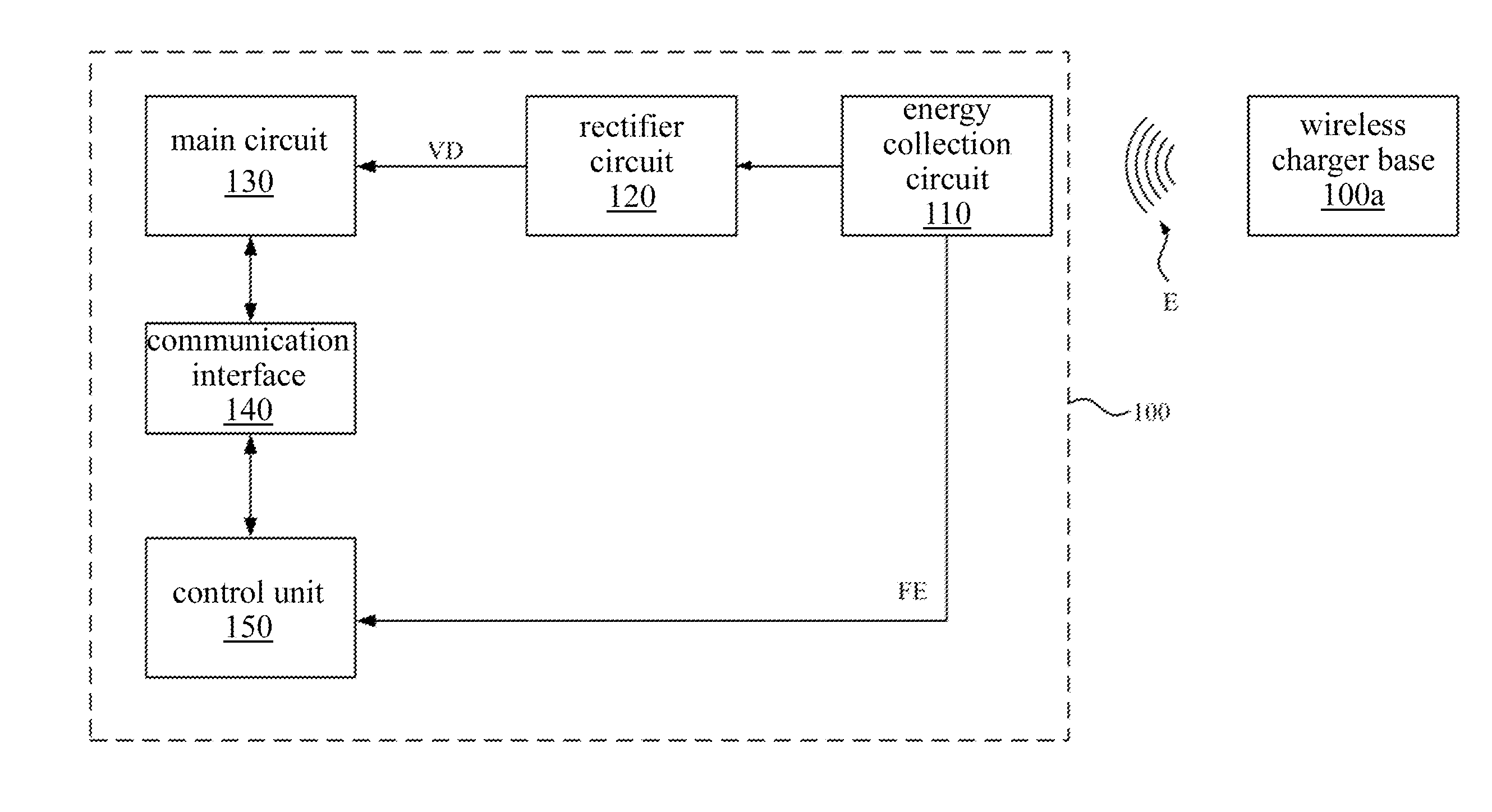
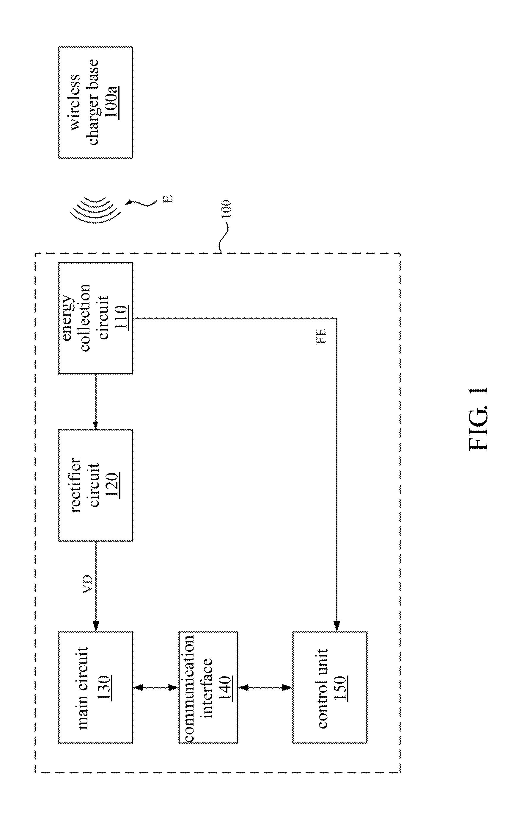
[0016]FIG. 1 is a schematic diagram showing an electronic device in an embodiment. In an embodiment, an electronic device 100 may be a notebook computer, a tablet computer or a smart phone, which is not limited herein.

[0017]As shown in FIG. 1, the electronic device 100 includes an energy collection circuit 110, a rectifier circuit 120, a main circuit 130, a communication interface 140 and a control unit 150.

[0018]When the electronic device 100 is placed closely to the wireless charger base 100a, the wireless charger base 100a starts to transmit the energy signal E to the energy collection circuit 110 via the transmission frequency FE.

[0019]The energy collection circuit 110 receives the energy signal E and transmits the energy signal E to the rectifier circuit 120. The rectifier circuit 120 is coupled to the energy collection circuit 110 and rectifies the energy signal E to generate the drive voltage VD. In an embodiment, the rectifier circuit 120 may be a half wave rectifier, a full...


PUM


Abstract

An electronic device includes an energy collection circuit, a rectifier circuit, and a control unit. The energy collection circuit receives an energy signal transmitted via transmission frequency from a wireless charger base. The rectifier circuit generates a drive voltage according to the energy signal. The control unit compares the drive voltage with a reference voltage, and compares the transmission frequency with a reference frequency. When the drive voltage is less than or equals to the reference voltage, or when the transmission frequency is lower than or equals to the reference frequency, the control unit outputs position deviation information. The electronic device detects the efficiency of the wireless charging, and reminds the user whether the position of the electronic device needs to be adjusted, which ensures an efficient charging.

Description

CROSS-REFERENCE TO RELATED APPLICATION[0001]This application claims the priority benefit of China application serial No. 201410604066.1, filed on Oct. 31, 2014. The entirety of the above-mentioned patent application is hereby incorporated by reference herein and made a part of specification.BACKGROUND OF THE INVENTION[0002]1. Field of the Invention[0003]The disclosure relates to an electronic device and, more particularly, to an electronic device with a wireless charging function.[0004]2. Description of the Related Art[0005]It is convenient for the users to charge the electronic devices without additional transmission lines. Thus, the wireless charging technology equipped in electronic devices is a recently trend.[0006]Generally, the electronic device is charged when placed at a wireless charger base. However, when the electronic device is not placed at an appropriate position of the base, the electronic device cannot be recognized and thus cannot be charged.[0007]When the position ...

Claims


Application Information

Patent Timeline
IPC IPC(8): H02J7/02
CPCH02J7/025H02J50/10H02J50/90H02J50/80H02J7/00034
Inventor HUANG, YI-MINGTU, WEI-CHENTSAI, MING-TINGHUNG, HSIANG-JUE
Owner ASUSTEK COMPUTER INC
Why Eureka
Try Eureka