

Fluid ejection device
- Summary
- Abstract
- Description
- Claims
- Application Information
AI Technical Summary
Benefits of technology
Problems solved by technology
Method used
Image

Examples
first embodiment
B. Piezoelectric Element Drive Circuit of First Embodiment
C. Power Recovery Module of First Embodiment
second embodiment
D. Piezoelectric Element Drive Circuit of Second Embodiment
E. Modified Embodiments
[0032]E-1. First Modified Embodiment
[0033]E-2. Second Modified Embodiment
A. Device Configuration
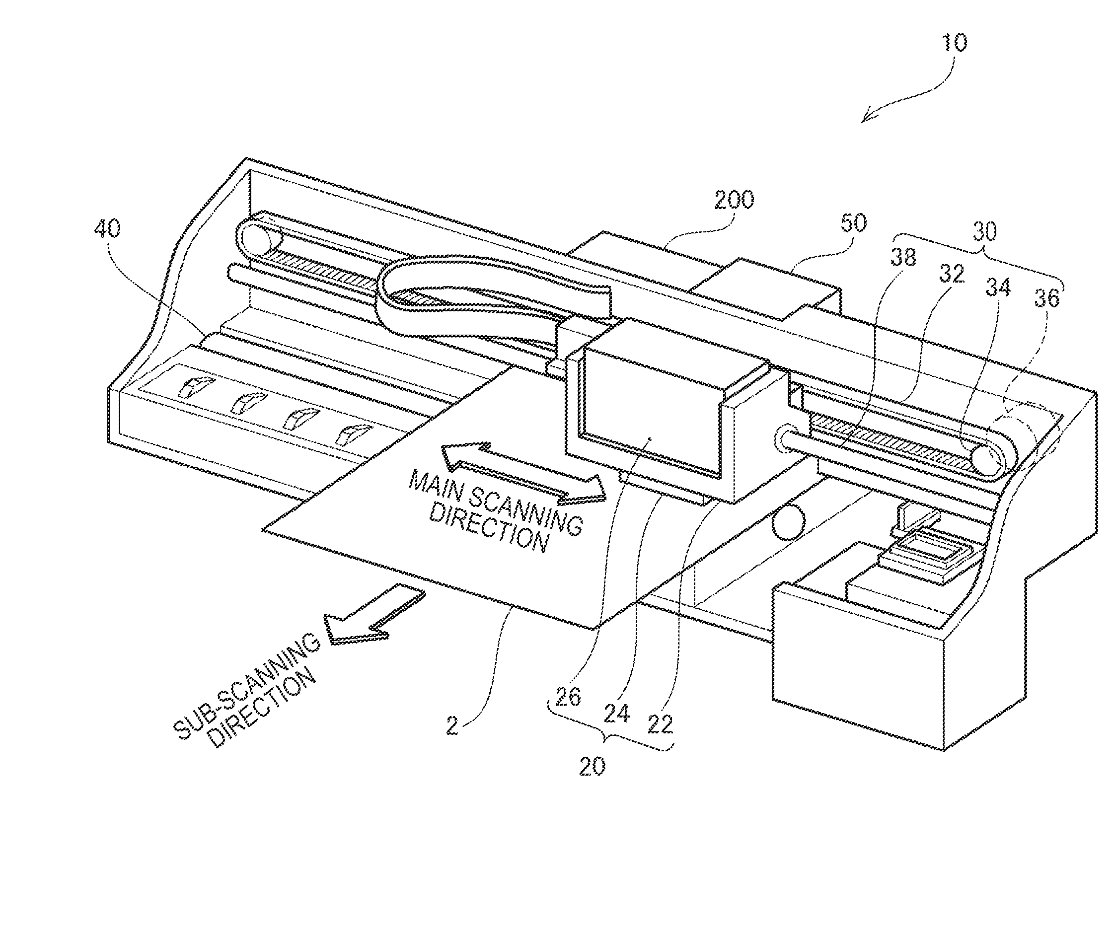
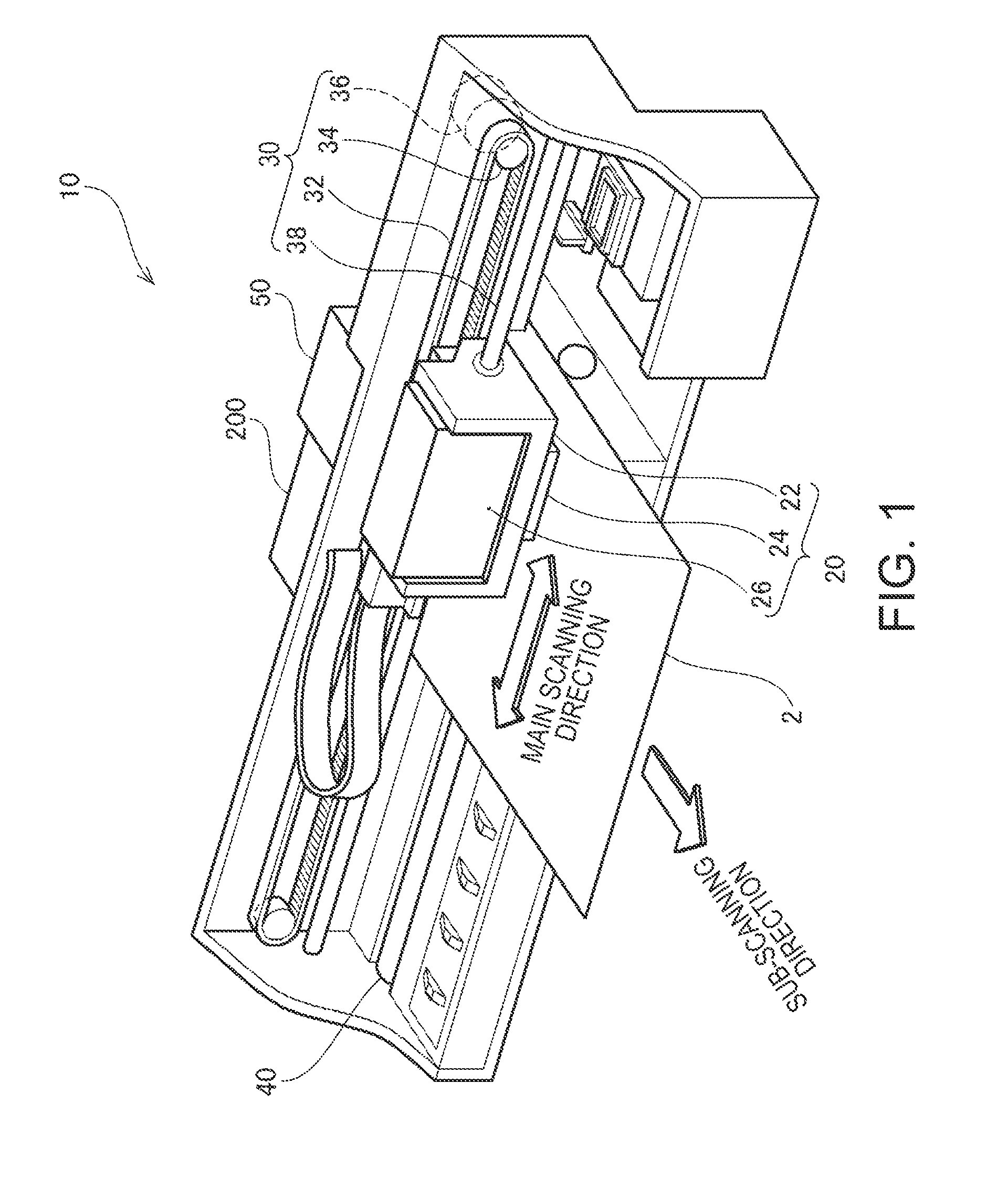
[0034]FIG. 1 is an illustration showing an outline configuration of a fluid ejection device of an embodiment using an ink jet printer. An ink jet cartridge 10 is configured of a carriage which forms ink dots on a printing medium 2 while reciprocating in a main scanning direction, a drive mechanism 30 which reciprocates the carriage 20, a platen roller 40 for carrying out a feed of the printing medium 2, and the like. An ink cartridge 26 containing ink, a carriage case 22 in which the ink cartridge 26 is loaded, an ejection head 24, mounted on a bottom side (the side facing the printing medium 2) of the carriage case 22, which ejects ink, and the like, are provided in the carriage 20. By guiding the ink inside the ink cartridge 26 to the ejection head 24, it is possible to eject an accurate amount of ink from...
first modified embodiment
E-1. First Modified Embodiment
[0063]The power recovery modules of the heretofore described embodiments have been described assuming that the power source and each of the capacitors are connected via the switches (refer to the switches indicated by A in FIG. 9). Connecting via rectifying devices such as diodes instead of the switches may further simplify the power recovery module configuration.
[0064]FIG. 11 is an illustration showing a power recovery module of a modified embodiment in which the power source and capacitors are connected with diodes. In the power recovery module of the modified embodiment, the capacitors C1 to C3 are connected to the power source via diodes D1 to D3 respectively. In the case of connecting the capacitors to the power source using diodes in this way, power is supplied from the power source to the capacitors, but no power flows from the capacitors to the power source. In has the same effect as connecting the capacitors and the power source with the switch...
PUM
 Abstract
Description
Claims
Application Information