Method and apparatus for attaching tissue to bone, including the provision and use of a novel knotless suture anchor system, including a novel locking element

a tissue and bone technology, applied in the field of surgical methods and equipment, can solve the problems of significant interference with patient comfort and lifestyle, pathology so severe that it is necessary for partial or total hip replacement, and the scope of procedures is generally limited

Active Publication Date: 2016-05-12
STRYKER CORP
View PDF2 Cites 29 Cited by
  • Summary
  • Abstract
  • Description
  • Claims
  • Application Information

AI Technical Summary

Benefits of technology

[0083]whereby, when the elongated body is disposed in a second object, and the first object extends through the window, and the locking element is thereafter moved proximally,

Problems solved by technology

In other cases, the pathology may be minor at the outset but, if left untreated, may worsen over time.
The pathology may, either initially or thereafter, significantly interfere with patient comfort and lifestyle.
In some cases, the pathology can be so severe as to require partial or total hip replacement.
A number of procedures have been developed for treating hip pathologies short of partial or total hip replacement, but these procedures are generally limited in scope due to the significant difficulties associated with treating the hip joint.
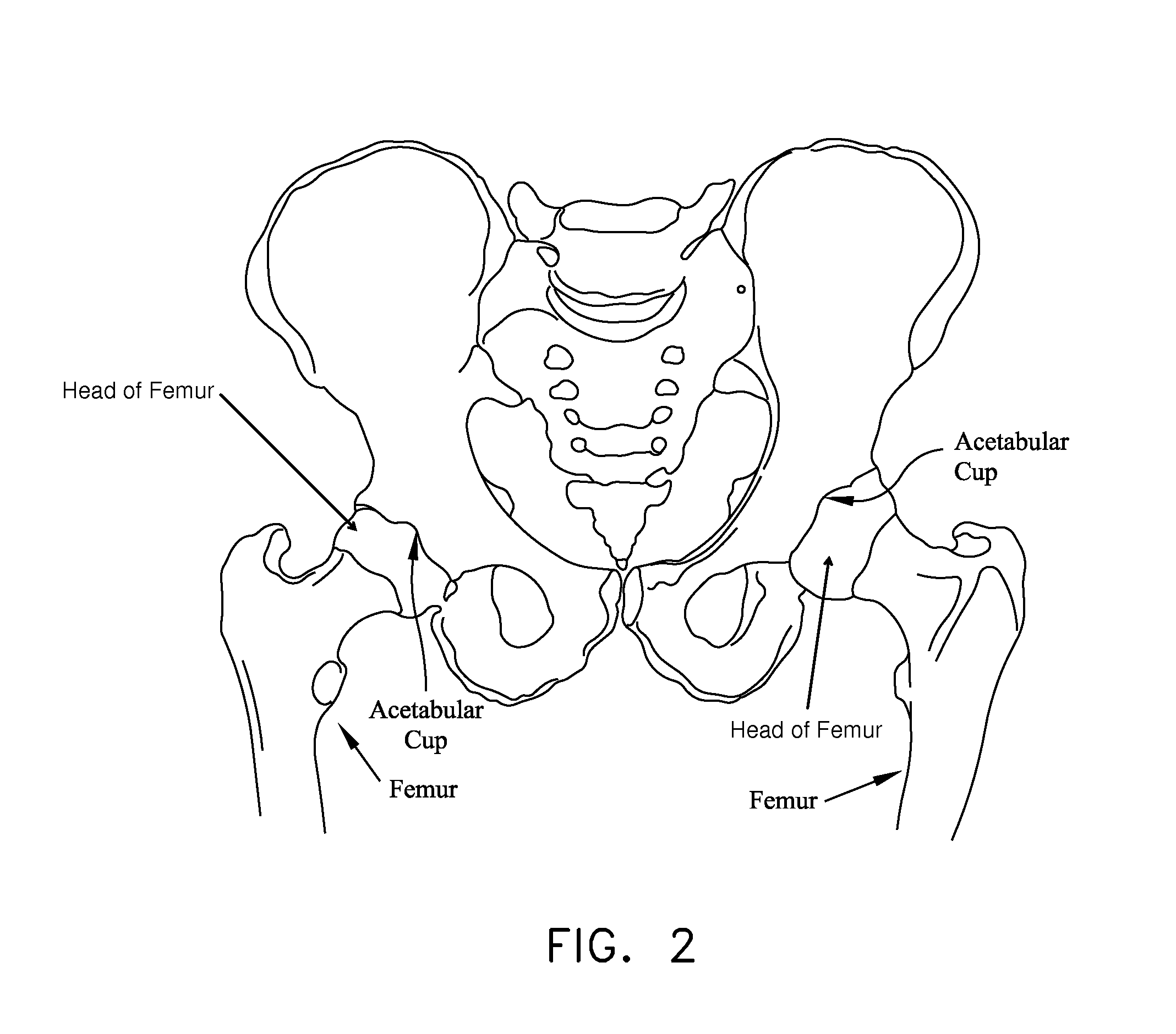
In some cases, and looking now at FIG. 13, this impingement can occur due to irregularities in the geometry of the femur.
In other cases, and looking now at FIG. 14, the impingement can occur due to irregularities in the geometry of the acetabular cup.
Impingement can result in a reduced range of motion, substantial pain and, in some cases, significant deterioration of the hip joint.
Defects of this type sometimes start out fairly small but often increase in size over time, generally due to the dynamic nature of the hip joint and also due to the weight-bearing nature of the hip joint.
Articular defects can result in substantial pain, induce and/or exacerbate arthritic conditions and, in some cases, cause significant deterioration of the hip joint.
More particularly, in many cases, an accident or sports-related injury can result in the labrum being torn away from the rim of the acetabular cup, typically with a tear running through the body of the labrum.
These types of labral injuries can be very painful for the patient and, if left untreated, can lead to substantial deterioration of the hip joint.
Unfortunately, minimally-invasive treatments for pathologies of the hip joint have lagged far behind minimally-invasive treatments for pathologies of the shoulder joint and the knee joint.
As a result, it is relatively difficult for surgeons to perform minimally-invasive procedures on the hip joint.
This limited access further complicates effectively performing minimally-invasive procedures on the hip joint.
In addition to the foregoing, the nature and location of the pathologies of the hip joint also complicate performing minimally-invasive procedures on the hip joint.
This makes drilling into bone, for example, significantly more complicated than where the angle of approach is effectively aligned with the angle at which the instrument addresses th

Method used


Image

  • Method and apparatus for attaching tissue to bone, including the provision and use of a novel knotless suture anchor system, including a novel locking element
  • Method and apparatus for attaching tissue to bone, including the provision and use of a novel knotless suture anchor system, including a novel locking element
  • Method and apparatus for attaching tissue to bone, including the provision and use of a novel knotless suture anchor system, including a novel locking element

Examples


Embodiment Construction

Knotless Suture Anchor System

[0132]Looking first at FIGS. 19 and 20, there is shown a novel knotless suture anchor system 5 formed in accordance with the present invention. Knotless suture anchor system 5 generally comprises a knotless suture anchor 10, an inserter 15 for inserting knotless suture anchor 10 in bone, and a suture threader 20 for threading a suture through knotless suture anchor 10 (and inserter 15) before the knotless suture anchor is deployed in bone.

[0133]Looking next at FIGS. 21-25, knotless suture anchor 10 generally comprises a body 25, a locking element 30 for radially expanding the body and securing a suture (not shown in FIGS. 21-25) to the body, and a pull rod 35 for moving locking element 30 proximally relative to body 25, whereby to simultaneously (i) radially expand the body so as to secure knotless suture anchor 10 to bone, and (ii) secure a suture to the body so as to secure that suture to knotless suture anchor 10 (and hence to the bone within which th...


PUM


Abstract

Apparatus for securing a first object to a second object, the apparatus comprising: an elongated body having a distal end, a proximal end, and a lumen extending between the distal end and the proximal end, the lumen comprising a distal section and a proximal section, the distal section of the lumen having a wider diameter than the proximal section of the lumen; a window extending through the side wall of the elongated body and communicating with the lumen, the window being disposed in the vicinity of the intersection between the distal section of the lumen and the proximal section of the lumen and being sized to receive a first object therein; an elongated element extending through the lumen of the elongated body, the elongated element comprising a proximal end and a distal end; and a locking element mounted to the distal end of the elongated element and disposed in the distal section of the lumen; whereby, when the elongated body is disposed in a second object, and the first object extends through the window, and the locking element is thereafter moved proximally, proximal movement of the locking element causes the locking element to capture the first object to the elongated body, whereby to secure the first object to the second object; wherein the elongated element comprises a pull line terminating in a loop; and wherein the locking element comprises at least one filament extending through the loop.

Description

REFERENCE TO PENDING PRIOR PATENT APPLICATIONS[0001]This patent application:[0002](1) is a continuation-in-part of pending prior U.S. patent application Ser. No. 14 / 876,091, filed Oct. 6, 2015 by Pivot Medical, Inc. and Jeremy Graul et al. for METHOD AND APPARATUS FOR ATTACHING TISSUE TO BONE, INCLUDING THE PROVISION AND USE OF A NOVEL KNOTLESS SUTURE ANCHOR SYSTEM (Attorney's Docket No. FIAN-8687 CON), which patent application in turn:[0003](A) is a continuation of prior U.S. patent application Ser. No. 13 / 830,501, filed Mar. 14, 2013 by Pivot Medical, Inc. and Jeremy Graul et al. for METHOD AND APPARATUS FOR ATTACHING TISSUE TO BONE, INCLUDING THE PROVISION AND USE OF A NOVEL KNOTLESS SUTURE ANCHOR SYSTEM (Attorney's Docket No. FIAN-8687), which patent application in turn:[0004](i) is a continuation-in-part of pending prior U.S. patent application Ser. No. 13 / 642,168, filed Dec. 26, 2012 by Chris Pamichev et al. for METHOD AND APPARATUS FOR RE-ATTACHING THE LABRUM TO THE ACETABULU...

Claims


Application Information

Patent Timeline
IPC IPC(8): A61B17/04
CPCA61B17/0401A61B17/0485A61B17/06166A61B2017/0042A61B2017/00477A61B2017/00986A61B2017/0403A61B2017/0404A61B2017/0409A61B2017/0412A61B2017/0414A61B2017/0424A61B2017/0438A61B2017/045A61B2017/0453A61B2017/0458A61B2017/06185A61B2090/037
Inventor KONRATH, MICHAELKAISER, WILLIAMPANDYA, SUDIPGRAUL, JEREMYBURLEY, J. BROOK
Owner STRYKER CORP
Why Eureka
Try Eureka