Liquid ejecting apparatus and wiping method thereof

a technology of liquid ejecting apparatus and wiping method, which is applied in the direction of printing mechanism, power drive mechanism, printing, etc., can solve the problem that the nozzle cannot eject liquid appropriately, and achieve the effect of reducing the amount of liquid remaining on the wiped surfa

Inactive Publication Date: 2016-05-12
SEIKO EPSON CORP
View PDF3 Cites 0 Cited by
  • Summary
  • Abstract
  • Description
  • Claims
  • Application Information

AI Technical Summary

Benefits of technology

[0021]In this case, the same effect as the liquid ejecting apparatus can be obtained. In the wiping method, at least one of the wiping at the first relative traveling speed and the wiping at the second relative traveling speed is preferably performed multiple times.
[0022]In this case, at least one of the wiping at the first relative tr

Problems solved by technology

In this case, the nozzle cannot eject liquid appropriately.
Furthermore, such a problem does not occur only in the case of wiping the liquid ejecting head o

Method used


Image

  • Liquid ejecting apparatus and wiping method thereof
  • Liquid ejecting apparatus and wiping method thereof
  • Liquid ejecting apparatus and wiping method thereof

Examples


Embodiment Construction

[0035]Hereinafter, an embodiment of the liquid ejecting apparatus is described in reference to drawings. An ink jet printer, as an example of liquid ejecting apparatus, prints onto a sheet, as an example of a target, by ejecting ink, as an example of liquid.

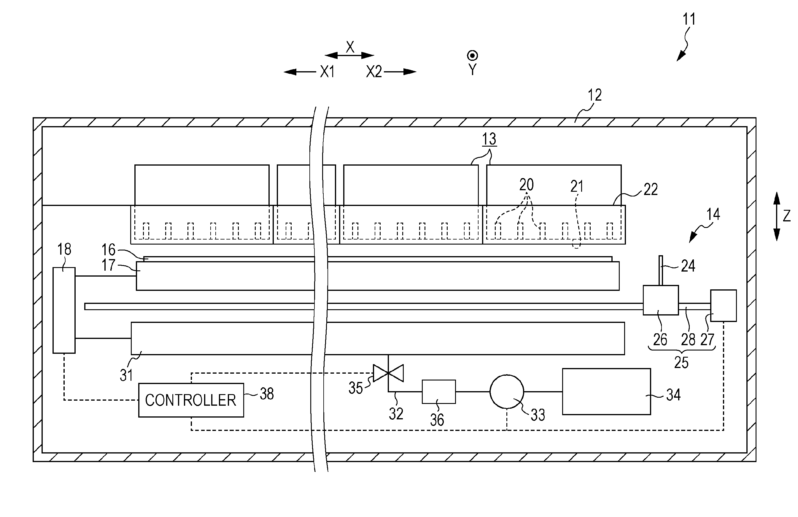
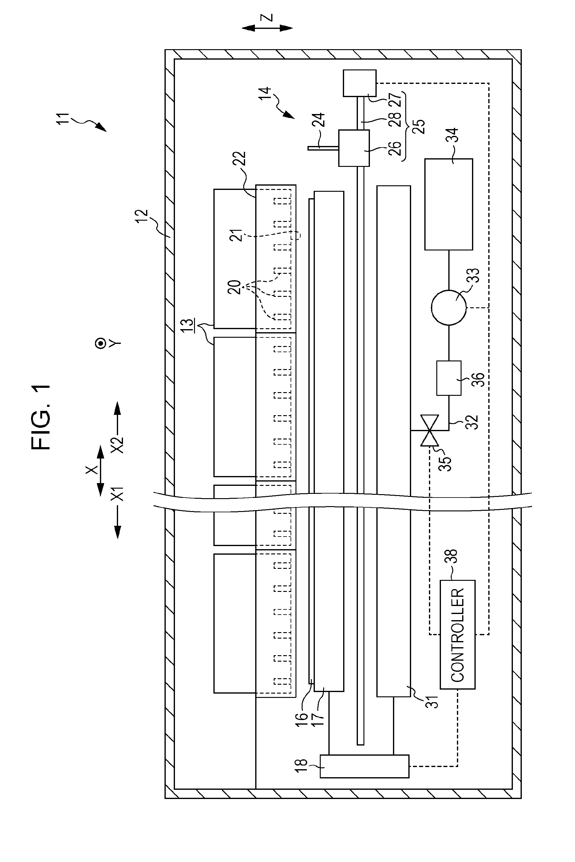
[0036]As illustrated in FIG. 1, a liquid ejecting apparatus 11 includes a casing unit 12, multiple liquid ejecting units 13 (for example, six) which are accommodated in the casing unit 12 and are arranged to be adjacent to each other in a parallel-arrangement direction X (left-right direction in FIG. 1), and a maintenance unit 14 which carries out maintenance for the liquid ejecting unit 13. In addition, the casing unit 12 accommodates a supporting frame 17 which supports a sheet 16, and a lifting / lowering mechanism 18 which lifts and lowers the supporting frame 17. In other words, the supporting frame 17 is provided to be able to travel between a supporting position (a position as shown in FIG. 1) where the supporting frame 17 s...


PUM


Abstract

There is provided a liquid ejecting apparatus including a liquid ejecting unit that has a nozzle row configured to have a plurality of nozzles lined up along a first direction, and a wiping portion that moves in a second direction intersecting the first direction such that the liquid ejecting unit is wiped, in which the liquid ejecting unit includes a plurality of nozzle rows configured to have space therebetween in the second direction, a convex portion placed between the nozzle rows in the second direction, and flat portions placed at both sides of the convex portion in the first direction, and the wiping portion wipes at a first relative travel speed to collect liquid attached to the liquid ejecting unit to the flat portion, and then wipes at a second relative travel speed faster than the first relative travel speed to move liquid attached to the flat portion.

Description

BACKGROUND[0001]1. Technical Field[0002]The present invention relates to a liquid ejecting apparatus, such as an ink jet printer, and a method of wiping the liquid ejecting apparatus.[0003]2. Related Art[0004]As an example of the liquid ejecting apparatus, ink jet printers has been known which eject ink (liquid) onto a sheet (a target) through nozzles of a liquid ejecting head (a liquid ejecting unit) so that an image or the like is printed. To maintain good liquid ejecting performance of the nozzles, such printers may have a wiper unit to remove ink mist and the like attached to a nozzle surface on which the nozzles of the liquid ejecting head are formed (for example, see JP-A-2013-216011).[0005]Moreover, the printer may have a convex portion provided on the nozzle surface to suppress contact between a sheet deformed due to liquid attached thereto and the nozzles. In this case, the nozzle surface having the convex portion is subject to a wiping operation with a liquid absorbing bod...

Claims


Application Information

Patent Timeline
IPC IPC(8): B41J2/165
CPCB41J2/16535B41J2/16538B41J25/3084
Inventor NAWANO, MASAHISA
Owner SEIKO EPSON CORP
Why Eureka
Try Eureka