Variable geometry heat exchanger apparatus

a heat exchanger and variable geometry technology, applied in indirect heat exchangers, lighting and heating apparatus, machines/engines, etc., can solve the problem of increasing the specific fuel consumption of engines

Active Publication Date: 2016-05-12
GENERAL ELECTRIC CO
View PDF5 Cites 28 Cited by
  • Summary
  • Abstract
  • Description
  • Claims
  • Application Information

AI Technical Summary

Benefits of technology

[0004]These and other shortcomings of the prior art are addressed by the present disclosure, ...

Problems solved by technology

For cruise conditions, such as during inflight, when the temperature of the surrounding air is lower and the air speed is higher than during other phases of flig...

Method used


Image

  • Variable geometry heat exchanger apparatus
  • Variable geometry heat exchanger apparatus
  • Variable geometry heat exchanger apparatus

Examples


first embodiment

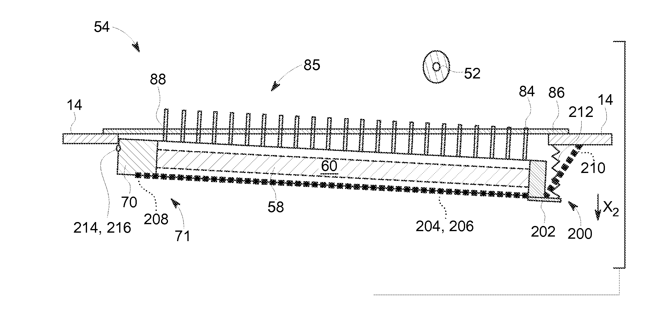
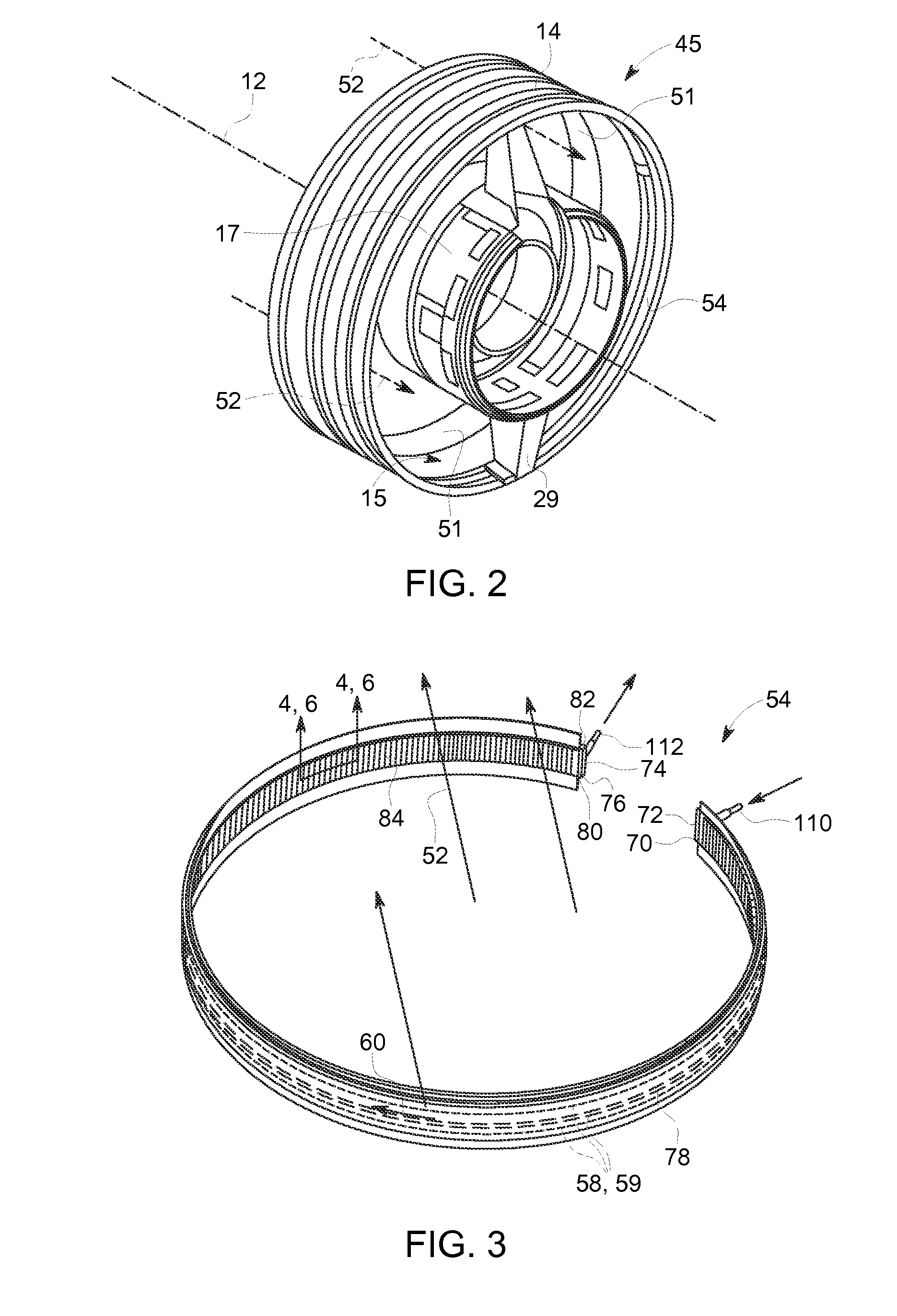
[0043]Referring now to FIGS. 4-7, illustrated is a passive automatic retraction and extension system 100 incorporated into the heat exchanger apparatus 54 of FIGS. 1-3. Illustrated in FIGS. 4 and 5 are partial cross-sectional views of the heat exchanger apparatus 54 during a first state of operation, such as in an engine oil system during a cruise condition of flight or such as in an engine generator system during a minimal load condition or condition in which minimal heat exchange is required. FIG. 4 is taken through line 4-4 of FIG. 3 and FIG. 5 taken through line 5-5 of FIG. 4. FIGS. 6 and 7 are partial cross-sectional views of the heat exchanger apparatus 54 during a second state of operation, such as in an engine oil system during a ground idle or climb condition of flight or such as in an engine generator system during a high load condition or condition in which an increase in heat exchange is required. FIG. 6 is taken through line 6-6 of FIG. 3 and FIG. 7 taken through line 7...

second embodiment

[0049]Referring now to FIGS. 8-11, illustrated is the passive automatic retraction and extension system, generally referenced 150, as indication of another embodiment that may be incorporated into the heat exchanger apparatus 54 of FIGS. 1-3. Illustrated in FIGS. 8 and 9 are partial cross-sectional views of the heat exchanger apparatus 54 during a first state of operation, such as when a lesser degree of heat exchange is required, with FIG. 8 taken in a direction generally similar to FIG. 4 and FIG. 9 taken through line 9-9 of FIG. 8. FIGS. 10 and 11 are partial cross-sectional views of the heat exchanger apparatus 54 during a second state of operation, such as when an increase in heat exchange is required, with FIG. 6 taken in a direction generally similar to FIG. 6 and FIG. 11 taken through line 11-11 of FIG. 10. Referring more specifically to FIGS. 8 and 9, illustrated is the heat exchanger apparatus 54 during the first state of operation in which the plurality of fins 84 are pos...


PUM


Abstract

A heat exchanger apparatus including a surface cooler and a passive automatic retraction and extension system coupled to the surface cooler. The surface cooler having disposed therein one or more fluid flow channels configured for the passage therethrough of a heat transfer fluid to be cooled. The heat transfer fluid in a heat transfer relation on an interior side of said one or more fluid flow channels. The surface cooler including a plurality of fins projecting from an outer surface thereof. The passive automatic retraction and extension system including a thermal actuation component responsive to a change in temperature of at least one of the heat transfer fluid and a cooling fluid flow so as to actuate a change in a geometry of the surface cooler. Further disclosed is an engine including the heat exchanger apparatus.

Description

BACKGROUND[0001]This invention relates generally to heat exchanger apparatus in gas turbine engines, and more particularly to a variable geometry surface cooler in such gas turbine engines.[0002]Aviation engines use heat transfer fluids, such as oil or fuel, to dissipate heat from engine components, such as engine bearings, electrical generators, and the like. Heat is typically rejected from the fluid to air by heat exchanger assemblies, such as fuel cooled oil coolers or air cooled surface oil coolers, to maintain oil temperatures at a desired ˜100° F.<T<300° F. In many instances, known heat exchanger assemblies, and more particularly surface coolers, typically found in aircraft engines are sized for ground idle (GI) conditions, when the temperature of the surrounding air is higher and the air speed is lower than during other phases of flight, such as found during inflight conditions. In addition, these known surface coolers are designed for use during top of climb conditions...

Claims


Application Information

Patent Timeline
IPC IPC(8): F02C7/14F02K3/02F28F13/00
CPCF02C7/14F02K3/025F28F13/00B64D33/12F02C7/18F28F27/02F28D1/047F28D7/08F28F1/12F28D2021/0021F28F2280/10F28D2021/0026F28F2255/04F02K3/06F05D2250/90F05D2300/505Y02T50/60
Inventor DIAZ, CARLOS ENRIQUEGERSTLER, WILLIAM DWIGHTSTORAGE, MICHAEL RALPHKENWORTHY, MICHAEL THOMAS
Owner GENERAL ELECTRIC CO
Why Eureka
Try Eureka