Eureka AIR delivers breakthrough ideas for toughest innovation challenges, trusted by R&D personnel around the world.

High angle screw fastener

a high angle screw and fastener technology, applied in the field of fasteners, can solve problems such as the penetration of the fastener further

Active Publication Date: 2016-05-12
ENGINEERED COMPONENTS COMPANY
View PDF8 Cites 0 Cited by
  • Summary
  • Abstract
  • Description
  • Claims
  • Application Information

AI Technical Summary

Benefits of technology

This patent text describes a new type of fastener for use in trailer construction. The new fastener has several modifications, including a smaller starting point diameter, which makes it easier for the operator to engage the tip of the screw in the pilot hole for the fastener and reduces the time required to fully drive the fastener into the floor board. Additionally, the new fastener has an increased starting location for the first starting thread, which allows for easier and quicker insertion of the fastener into the pilot hole. This fastener is easier to insert, drives in easier, and reduces fatigue and effort required on the part of the person driving the fasteners, improving efficiency and productivity of the trailer assembly process. Furthermore, the new fastener has an enlarged diameter to prevent it from pulling through the first material and a drive recess to give it ease of driving without cam out and prevent unauthorized tampering with the fastener. Overall, this new fastener provides improved performance and efficiency in trailer construction.

Problems solved by technology

This will provide a higher angled thread which will cause the fastener to be drawn into the material more quickly than current fasteners, however, not so fast as to prevent the fastener from being able to cut into metal and to pull itself into the metal.
Second, the smaller diameter of the tip means that the fastener penetrates further into the floor board before driving of the fastener begins.

Method used


Image

  • High angle screw fastener
  • High angle screw fastener

Examples


Embodiment Construction

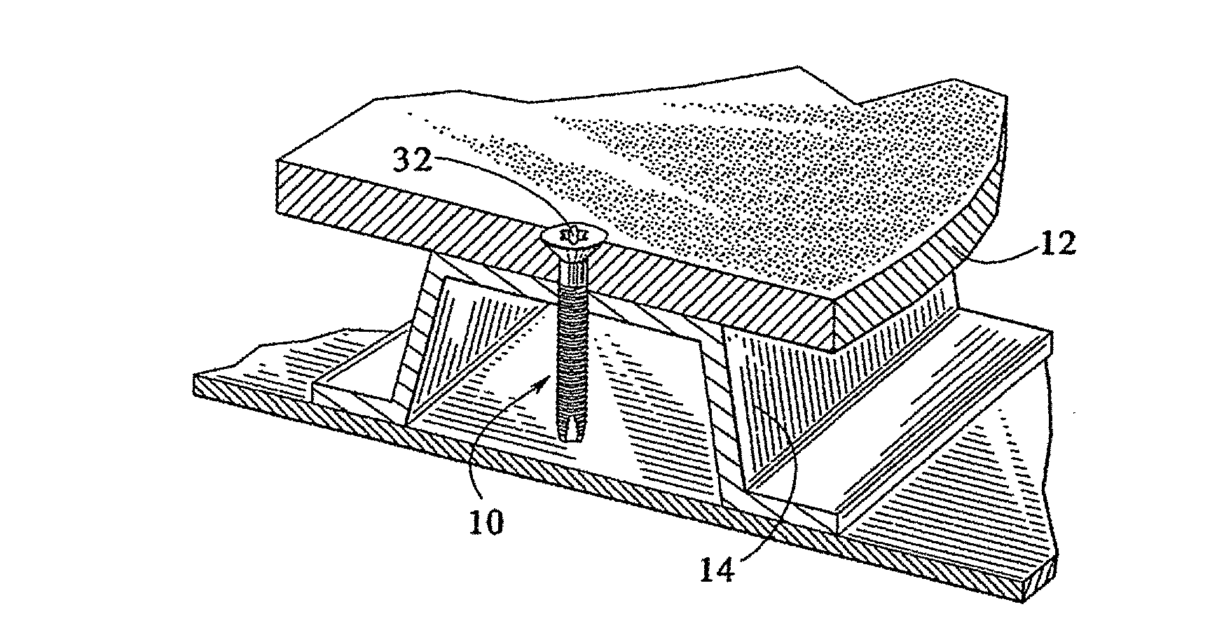
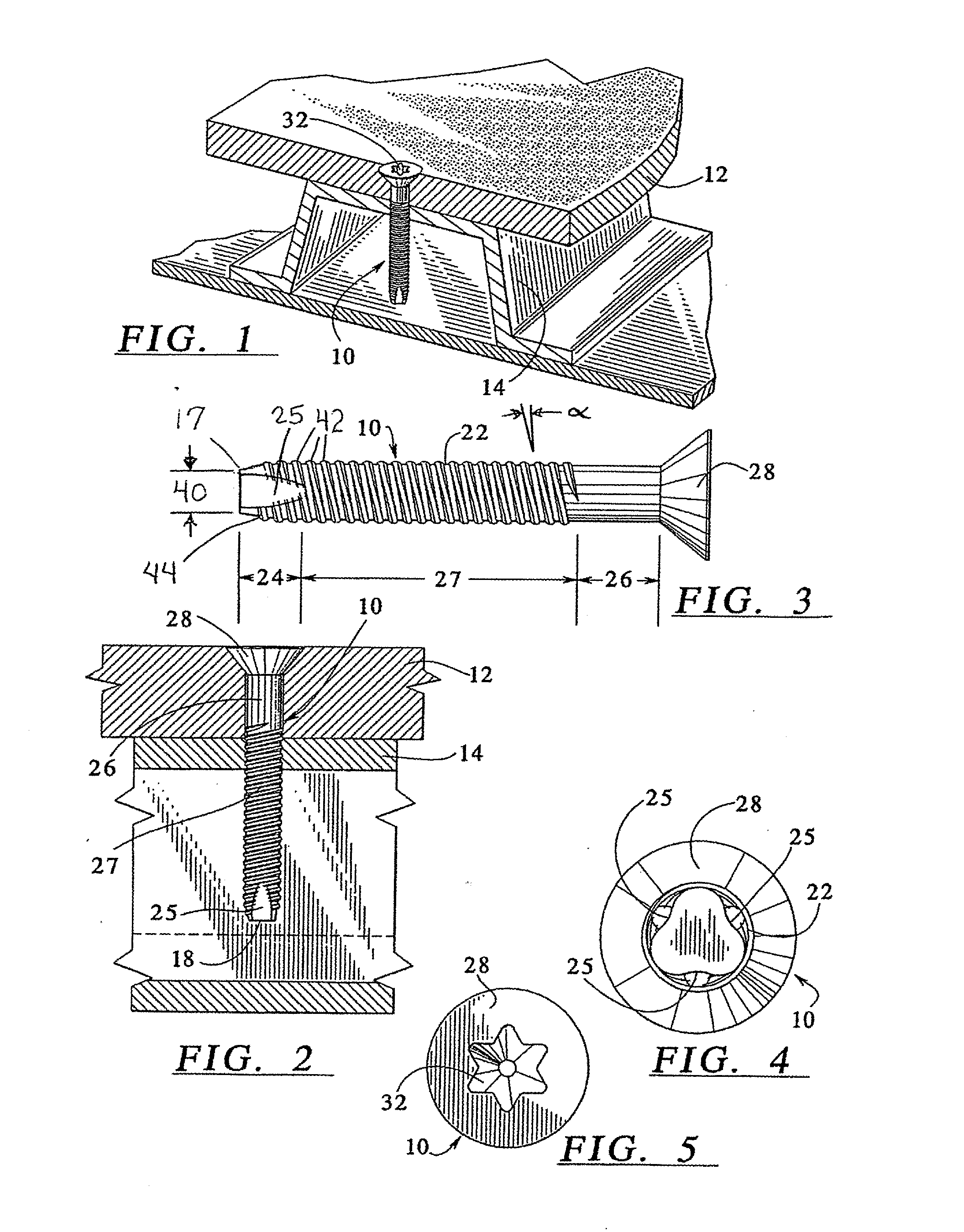
[0019]FIG. 1 illustrates an improved fastener embodying the principles of the present invention generally at 10. Although a fastener such as that disclosed and described can be used in many environments, for purposes of disclosure of the invention, one particular environment in which the fastener finds particular utility is shown. Such an environment is to secure a first or surface material, such as a floor board 12 generally formed of aluminum, hard wood or plastic, to a metal support 14, generally a channel member, frame or metal plate in the interior of a semi-trailer truck or truck body.

[0020]The fastener 10 itself is shown in greater detail in FIGS. 2-5.

[0021]A shank 22 of the fastener 10 includes a tip 17 with a trilobular or quadlobular thread tapping point 18 which rolls threads rather than cutting threads for a tighter fit. The thread tapping point 18 has a trilobular or quadlobular portion 24 with three or four flats 25 provided at the tip 17 and three or four separate thr...


PUM


Abstract

A threaded fastener for securing a first material to a support comprising a tapping point at a first end and a threaded shank with multiple separate leads. An end diameter of a fastener tip is in the range of 0.210 to 0.190 inches, the tapping point starts away from an end of the tip by a range of 0.320 to 0.40 inches, and the threads are arranged on the shank to provide a range of about 16½ to 17½ threads per inch for a 5 / 16 inch diameter fastener and about 18½ to 19½ threads per inch for a ¼ inch diameter fastener. A second portion of the shank, distal from the tap screw point, is unthreaded, and a head at an end opposite the tap screw point has an enlarged diameter and a countersunk shape to reduce the likelihood of pull through of the fastener through said first material.

Description

BACKGROUND OF THE INVENTION[0001]The present invention relates to a fastener, and in particular to a screw type threaded fastener used in securing two items together, such as a floor board to a truck body, or other similar application.[0002]In certain environments, for example in the application of a wood or plastic material wall to metal channels, frames or plates in the interior of a semi-trailer truck body, threaded fasteners are used which need to address many different problems.[0003]The threaded fastener should have some means for remaining secured to the metal frame so that the fastener will not come loose in the high vibration environment in which it is used. Also, it is desirable for the fastener to thread quickly into the materials to be fastened together.[0004]One fastener that addresses some of these problems is disclosed in U.S. Pat. No. 5,964,560, assigned to the assignee of the present application. That patent discloses a threaded fastener in which a shank of the scre...

Claims


Application Information

Patent Timeline
Patent Type & Authority Applications(United States)
IPC IPC(8): F16B25/10F16B23/00
CPCF16B23/003F16B25/10F16B25/0021F16B25/0031F16B25/0068F16B25/0084F16B35/06
Inventor HENRICKSEN, JR., ARNE
Owner ENGINEERED COMPONENTS COMPANY
Why Eureka
Eureka Blog
Learn More