
Additive manufacturing techniques and systems to form composite materials

a technology of additive manufacturing and composite materials, applied in the direction of 3d object support structures, metal-working apparatus, auxiliary shaping apparatus, etc., can solve the problem of not being able to change the material at various points of production to form more complex composites, although possible, and not desirabl

Active Publication Date: 2016-05-19
ORBITAL COMPOSITES INC
View PDF2 Cites 102 Cited by
  • Summary
  • Abstract
  • Description
  • Claims
  • Application Information

AI Technical Summary

Benefits of technology

The patent text describes various embodiments of a printer and a method for molding composite materials using the printer. The printer includes an extruder head with two distribution channels and a priming chamber, a heating element, and a nozzle. The method involves injecting a material into a mold and using a shaping actuator to control the distribution of the material. The printer can also include a fiber dispensing head for dispensing fibers onto a support structure. The patent also describes a method of forming a layered composite structure by extruding materials over a support structure and dissolving a highly soluble material. The patent also describes an insertion actuator for a printer and a method of forming a material structure on a surface of an object by depositing materials in a specific way. The technical effects of the patent text include improved control over the distribution of materials and the ability to mold composite materials with greater precision.

Problems solved by technology

Changing the material at various points of production to form more complex composites, although possible, is not desirable due to the significant time it takes to re-tool the extruder head and make the appropriate adjustments to achieve a high quality composite object.

Method used


Image

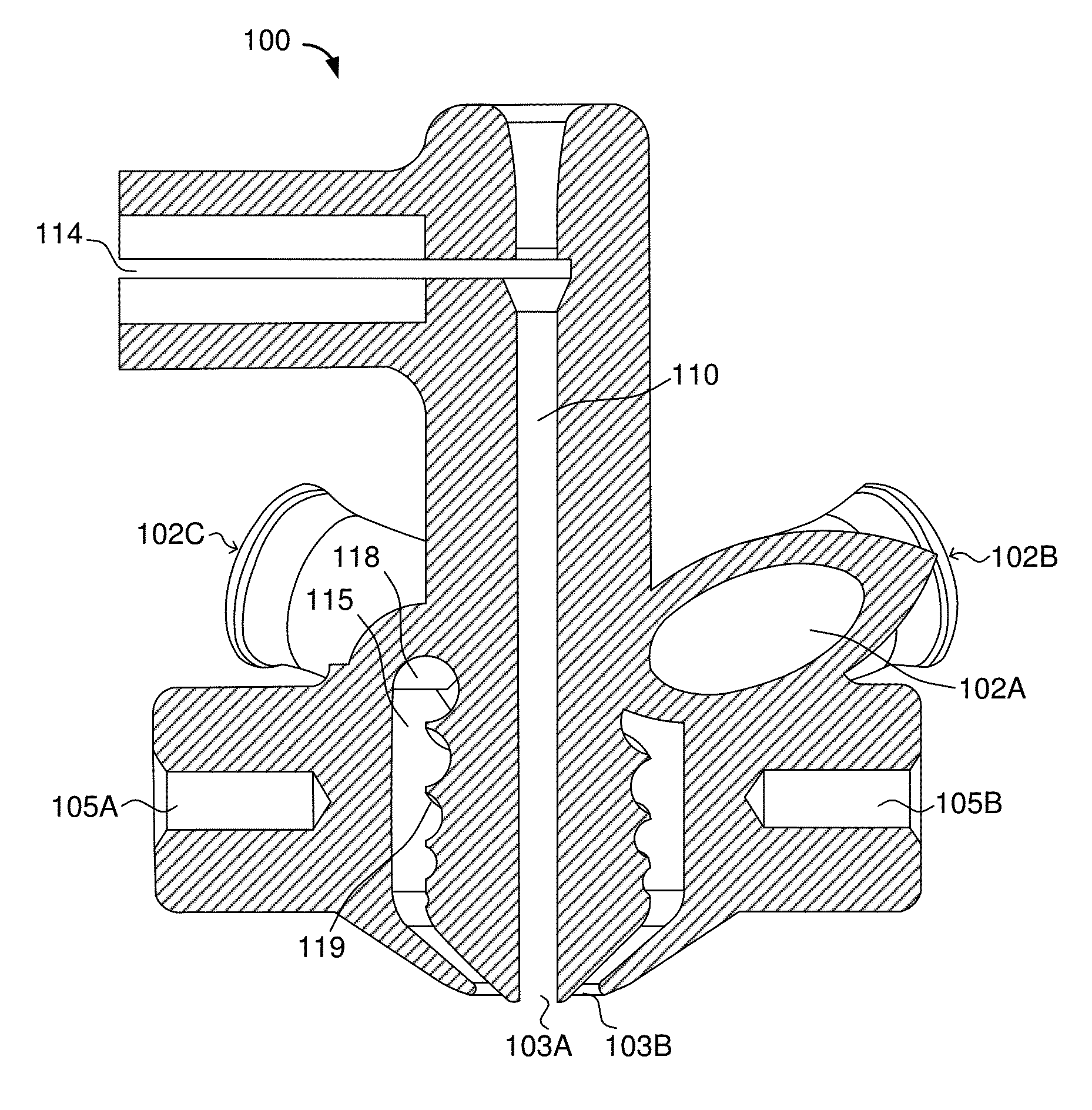
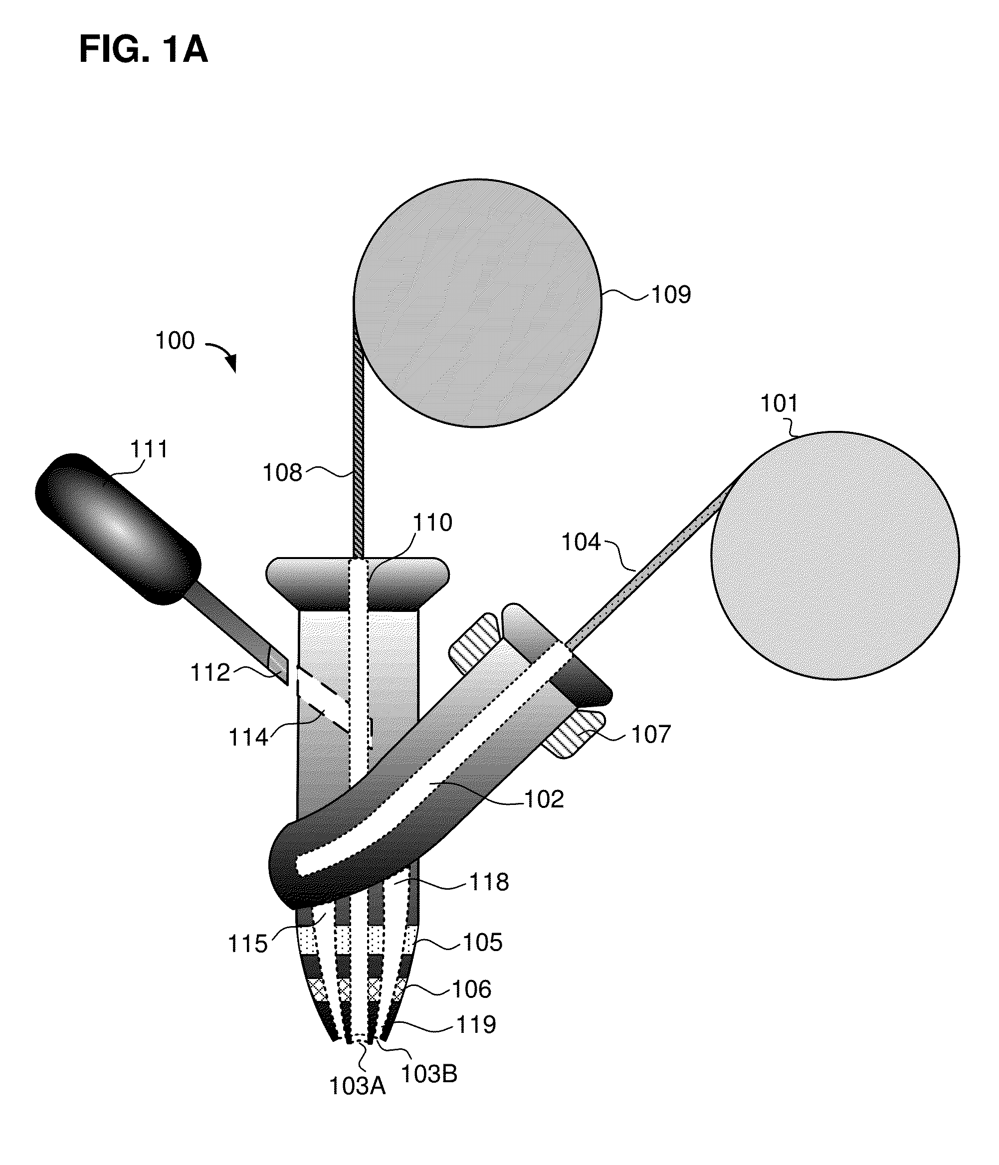
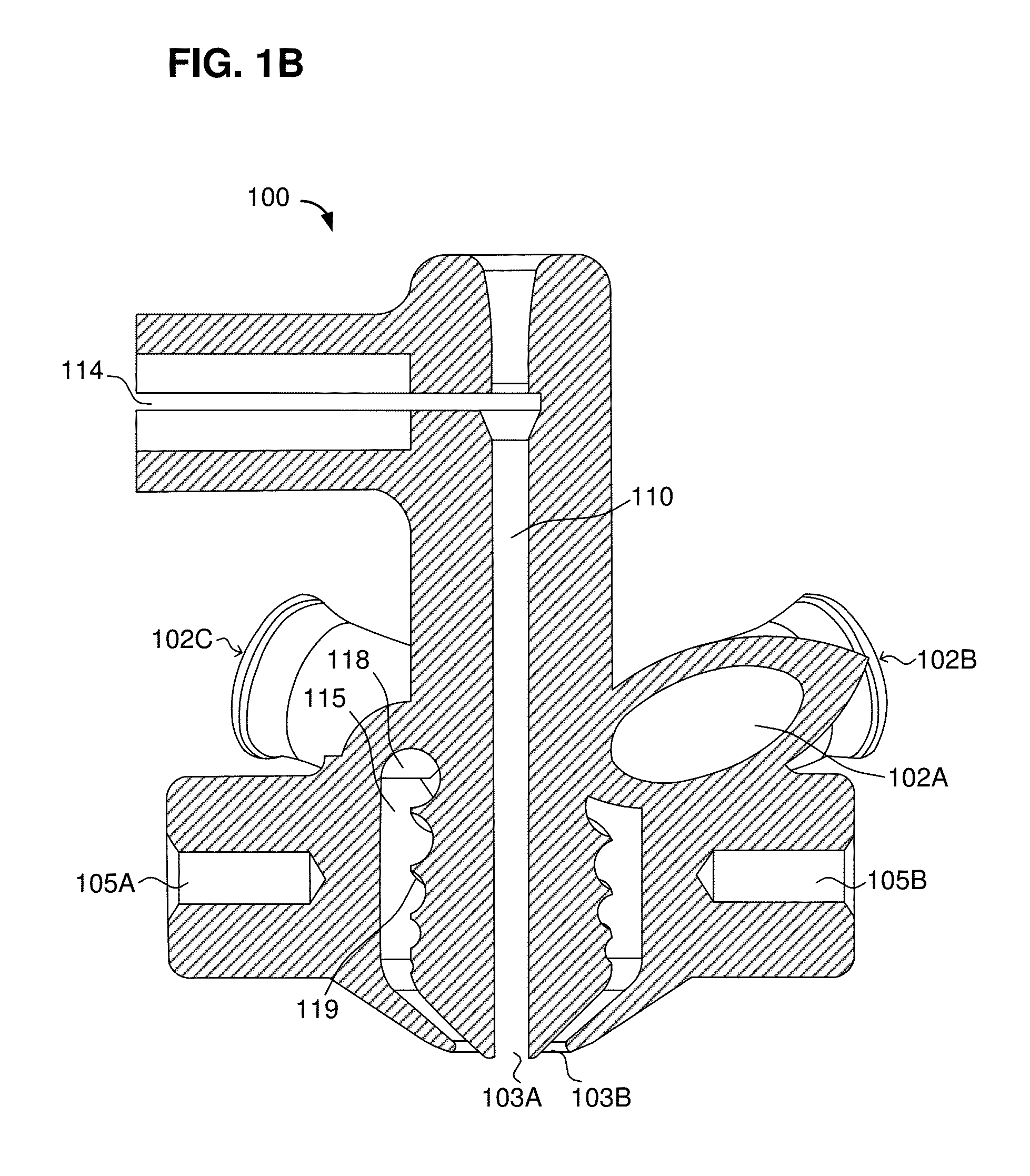
  • Additive manufacturing techniques and systems to form composite materials
  • Additive manufacturing techniques and systems to form composite materials
  • Additive manufacturing techniques and systems to form composite materials

Examples


Embodiment Construction

[0051]The following description is presented to enable a person of ordinary skill in the art to make and use the various embodiments. Descriptions of specific devices, assemblies, techniques, and applications are provided as examples. Various modifications to the examples described herein will be readily apparent to those of ordinary skill in the art, and the general principles defined herein may be applied to other examples and applications without departing from the spirit and scope of the various embodiments. Thus, the various embodiments are not intended to be limited to the examples described herein and shown, but are to be accorded the scope consistent with the claims.

[0052]Various embodiments are described below relating to adaptive fabrication (e.g., three-dimensional printing) of complex composite materials. As used herein, “3D printing” refers to adding material layer-by-layer to produce a solid three-dimensional object that includes forming successive two-dimensional laye...


PUM

PropertyMeasurementUnit
angleaaaaaaaaaa
angleaaaaaaaaaa
angleaaaaaaaaaa

Abstract

A printer system may include a coaxial extruder head that extrudes a core, a bulk, and / or a core and bulk cladding to form complex structures without retooling. The coaxial extruder head may include a distribution channel with an entrance and an exit, a priming chamber that surrounds the distribution channel. The priming chamber may include an outlet and a first inlet, a heating element thermally connected to the priming chamber, and a nozzle connected to the outlet of the priming chamber. Further, the nozzle may converge from the outlet of the priming chamber to an orifice of the nozzle. In addition, the exit of the distribution channel may be disposed at the orifice of the nozzle. This structure facilitates extruding a core and cladding type composite from the extruder head.

Description

CLAIM OF PRIORITY[0001]The present application claims priority to Provisional Application No. 62 / 079,923, entitled “COAXIAL EXTRUSION TOOL HEAD FOR 3D PRINTERS WITH ACTIVE MOLDING AND INJECTION MOLDING,” filed Nov. 14, 2014, and Provisional Application No. 62 / 148,174, entitled “COAXIAL EXTRUSION TOOL, 3D EXTRUDER AND FILAMENT WINDER TECHNIQUE, AND FORMING 3D STRUCTURES WITH HIGHLY SOLUBLE MATERIALS,” filed Apr. 15, 2015; each of which is hereby incorporated by reference in its entirety.BACKGROUND[0002]The present disclosure relates generally to three-dimensional (3D) printers, and more specifically to the devices, assemblies and techniques to adaptively form complex composite materials.[0003]Most 3D printers rely on an extruder head to deposit a thin heated bead of material to specified layers to additively form an object. The extruder head moves both horizontally and vertically to guide the placement for each layer of the heated bead of material so that the added material selective...

Claims


Application Information

Patent Timeline
Patent Type & Authority Applications(United States)
IPC IPC(8): B29C67/00B29C48/05B29C48/30B29C48/345
CPCB29C67/0088B33Y50/00B33Y30/00B33Y50/02B29C64/209B29C64/118B29C64/194B29C48/02B29C48/05B29C48/21B29C48/304B29C48/0021B29C48/266B29C48/865B29K2101/12B29L2031/16B29C64/218B29C64/393B29B7/90
Inventor NIELSEN-COLE, COLEFREI, JAMES
Owner ORBITAL COMPOSITES INC
Learn More