
System for calibrating a blood pressure measurement based on vascular transit of a pulse wave

a pulse wave and blood pressure measurement technology, applied in the field of system for calibrating a blood pressure measurement based on vascular transit of a pulse wave, can solve the problems of affecting the accuracy of blood pressure measurement, and limiting the utility of cuff-based methods in certain clinical situations

Active Publication Date: 2016-05-26
SOTERA WIRELESS
View PDF3 Cites 38 Cited by
  • Summary
  • Abstract
  • Description
  • Claims
  • Application Information

AI Technical Summary

Benefits of technology

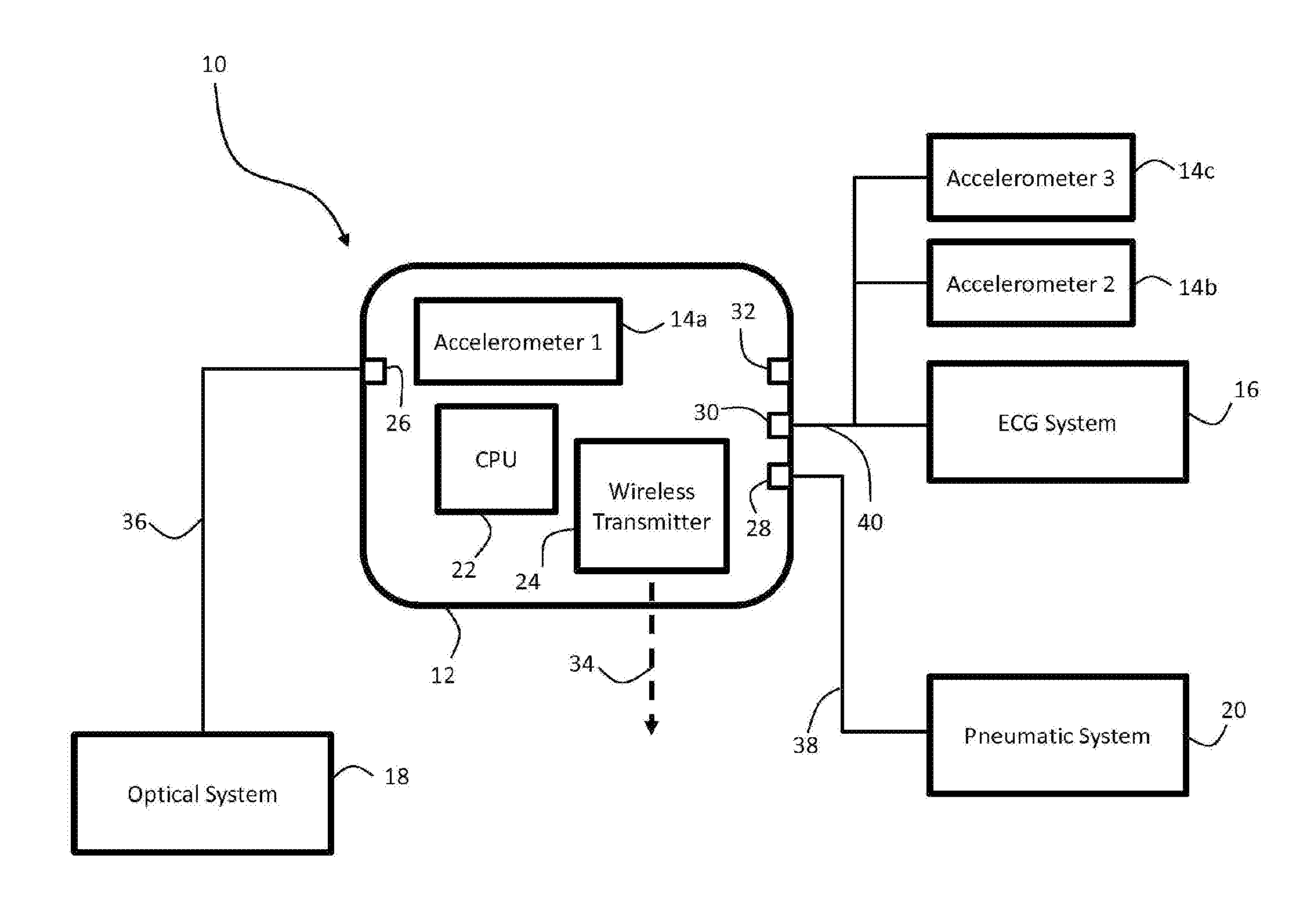
The present invention provides a system and method for calibrating a body-worn vital sign monitor that measures blood pressure and other vital signs using pulse pressure waves. The system includes sensors that measure pulse arrival time and electrocardiogram signals, as well as an inflatable cuff that measures pressure waveforms during inflation. The processing component analyzes these waveforms to determine a calibration that accounts for patient-dependent properties, such as arterial compliance. The system can also use pulse wave velocity to determine blood pressure, and can alert medical professionals if the patient's blood pressure is beginning to decrease or if the patient's heart rate is beginning to increase. The system is designed to provide accurate and continuous blood pressure readings, and can help prevent medical complications and alert medical professionals in a timely manner.

Problems solved by technology

However, cuff-based methods have some disadvantages that limit their utility in certain clinical situations.
Additionally, the inflation of the cuff may disturb the patient and the consequences of these disturbances are alterations of the BP and undesired arousal of the patient during sleep.

Method used


Image

  • System for calibrating a blood pressure measurement based on vascular transit of a pulse wave
  • System for calibrating a blood pressure measurement based on vascular transit of a pulse wave
  • System for calibrating a blood pressure measurement based on vascular transit of a pulse wave

Examples


Embodiment Construction

System Overview

[0030]For purposes of the present application, the following abbreviations apply:

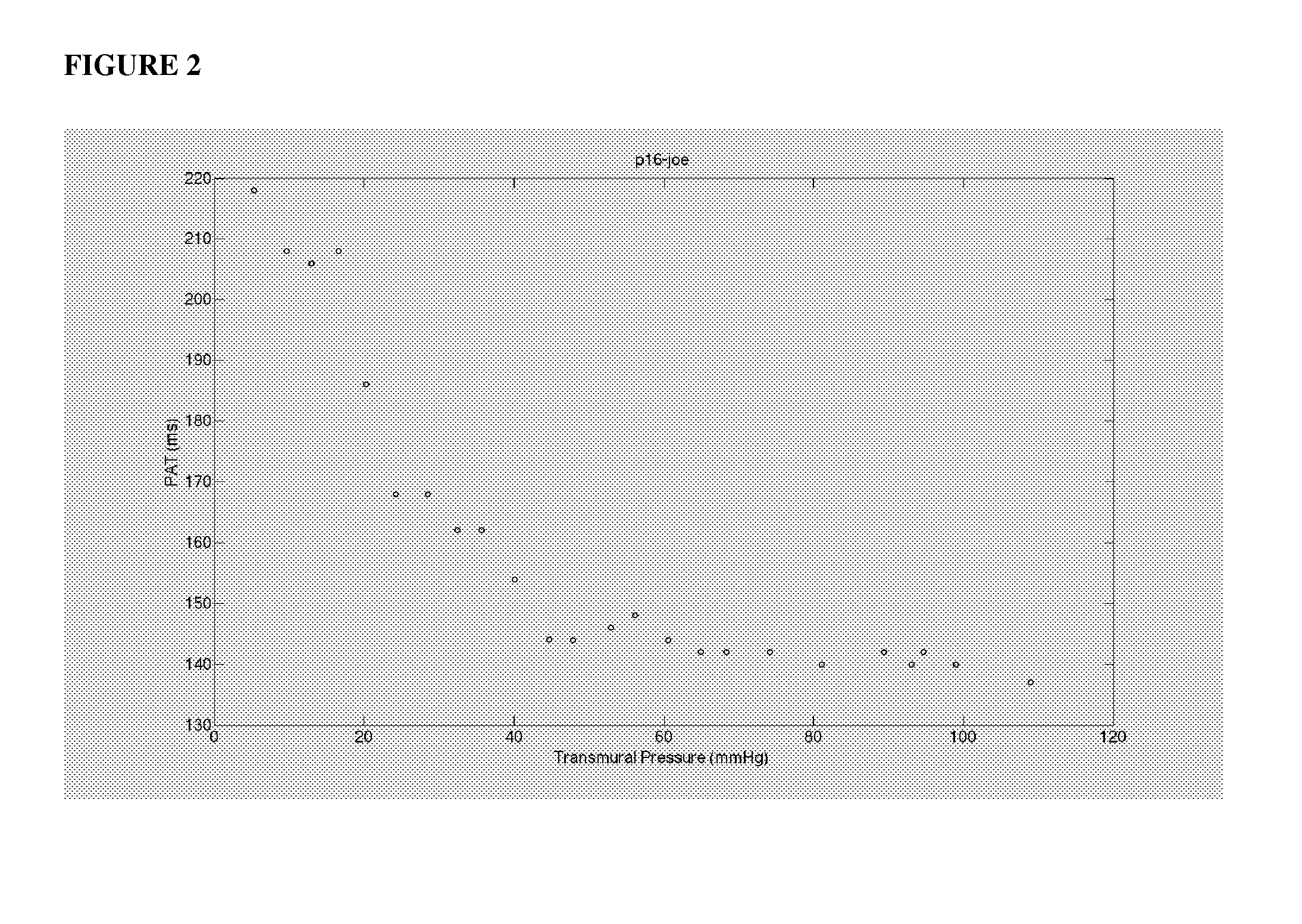
cNIBPAn abbreviation for continuous non-invasive blood pressureECGAn abbreviation for the ElectrocardiogramPPGAn abbreviation for the PhotoplethysmogramPWVAn acronym for Pulse Wave Velocity. PWV is the speed atwhich a pressure pulse travels along an arterial pathway.PATAn acronym for Pulse Arrival Time. PAT is the time differencebetween the onset of the Infrared PPG signal and the peak of theECG QRS complex for a single cardiac cycle.VTTAn acronym for Vascular Transit Time. VTT is the time requiredby a pressure pulse to travel between two locations along anarterial pathway.PEPAn acronym for Pre-ejection Period. PEP is the time differencebetween the opening of the aortic valve and the electrical activityof the heart. It consists of a period of electromechanical delayand a period of isovolumic contraction in the left ventricle.PtmAn abbreviation for transmural pressure. Ptm is the pressurea...


PUM


Abstract

The invention provides a system and method for measuring vital signs (e.g. SYS, DIA, SpO2, heart rate, and respiratory rate) and motion (e.g. activity level, posture, degree of motion, and arm height) from a patient. The system features: first and second sensors configured to independently generate time-dependent waveforms indicative of one or more contractile properties of the patient's heart; and a cuff-based oscillometric module. A processing component, typically worn on the patient's body and featuring a microprocessor, receives the time-dependent waveforms generated by the different sensors and processes them to determine patient-specific calibration values for use in a continuous blood pressure measurement based on pulse wave velocity (PWV).

Description

[0001]The present application claims priority to U.S. Provisional Application 62 / 040,958 filed Aug. 22, 2014, which is hereby incorporated in its entirety including all tables, figures, and claims.BACKGROUND OF THE INVENTION[0002]Non-invasive measurement of blood pressure (BP) using cuff-based methods provides adequate data for many applications in medicine. However, cuff-based methods have some disadvantages that limit their utility in certain clinical situations. For example, as cuff-based methods are by definition a discontinuous measurement of blood pressure, in BP that occur between measurements are missed. Additionally, the inflation of the cuff may disturb the patient and the consequences of these disturbances are alterations of the BP and undesired arousal of the patient during sleep.[0003]An alternative approach relates to a continuous, non-invasive and indirect measurement of BP based on the vascular transit of a pulse pressure wave. A number of variables been described in...

Claims


Application Information

Patent Timeline
IPC IPC(8): A61B5/021A61B5/026A61B5/0402A61B5/00A61B5/0205A61B5/022A61B5/02A61B5/332
CPCA61B5/02125A61B5/02233A61B5/026A61B5/02028A61B5/7278A61B5/02416A61B5/0402A61B5/7225A61B2562/0219A61B2560/0223A61B5/0205A61B5/02225A61B5/11A61B5/332A61B5/33
Inventor MCCOMBIE, DEVINZHANG, GUANQUN
Owner SOTERA WIRELESS
Learn More