
Systems and methods for determining optimum putting speed and angle

a technology of angle and putting speed, applied in the field of golf, can solve the problems of difficulty for the player to account for ground conditions and varying slopes, gps devices providing little benefit, and general inability of average golfers to use caddies, etc., and achieve the effect of less computational intensive, less expensive, and improved accuracy of calculation of each reverse path

Inactive Publication Date: 2016-05-26
DENNING ADAM +1
View PDF1 Cites 1 Cited by
  • Summary
  • Abstract
  • Description
  • Claims
  • Application Information

AI Technical Summary

Benefits of technology

The invention is an electronic device that can help golfers improve their putting by providing speed and angle information. It can be used as a dedicated golf aid or in general-purpose electronic devices like apps. Compared to existing methods, the invention is less expensive and can provide results faster, which can speed up play.

Problems solved by technology

Even when an accurate measurement is obtained, it can be difficult for the player to account for ground conditions and varying slopes of some greens.
However, caddies are generally not available for the average golfer.
However, when putting or chipping on the green, where both the direction and force of the shot must be precisely determined, such GPS devices provide little benefit.
However, as stated above, these devices provide little benefit once the ball is on or in close proximity to the green.

Method used


Image

  • Systems and methods for determining optimum putting speed and angle
  • Systems and methods for determining optimum putting speed and angle
  • Systems and methods for determining optimum putting speed and angle

Examples


Embodiment Construction

[0040]A description of embodiments of the present invention will now be given with reference to the Figures. It is expected that the present invention may take many other forms and shapes, hence the following disclosure is intended to be illustrative and not limiting, and the scope of the invention should be determined by reference to the appended claims.

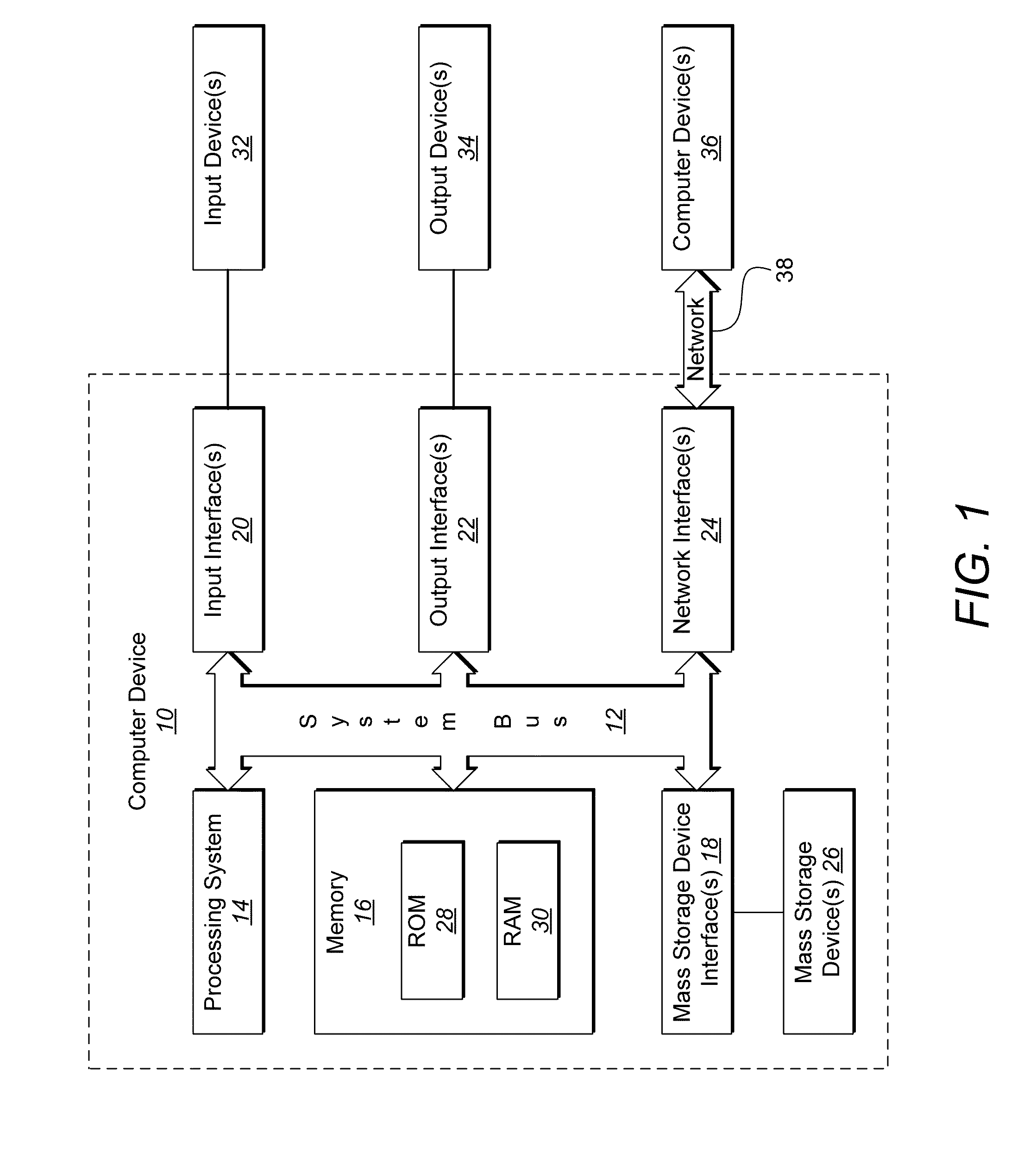
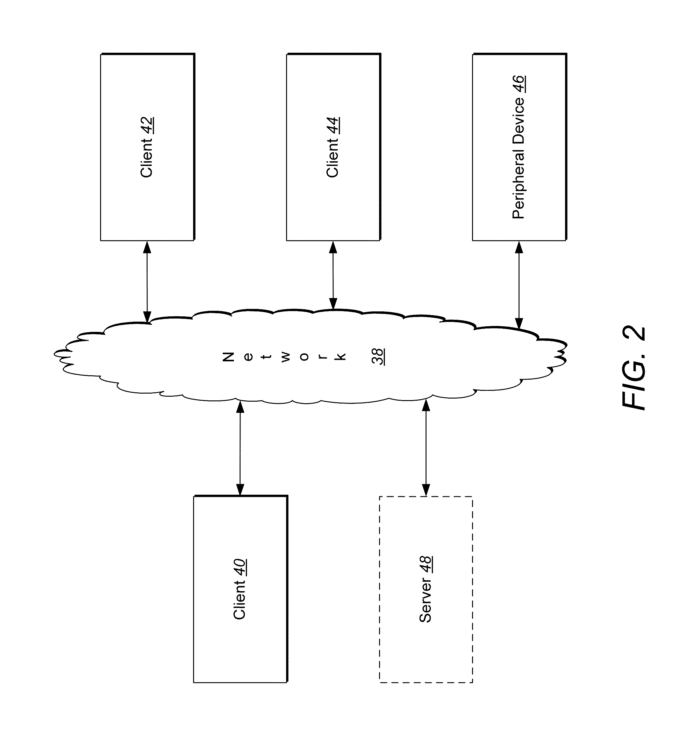
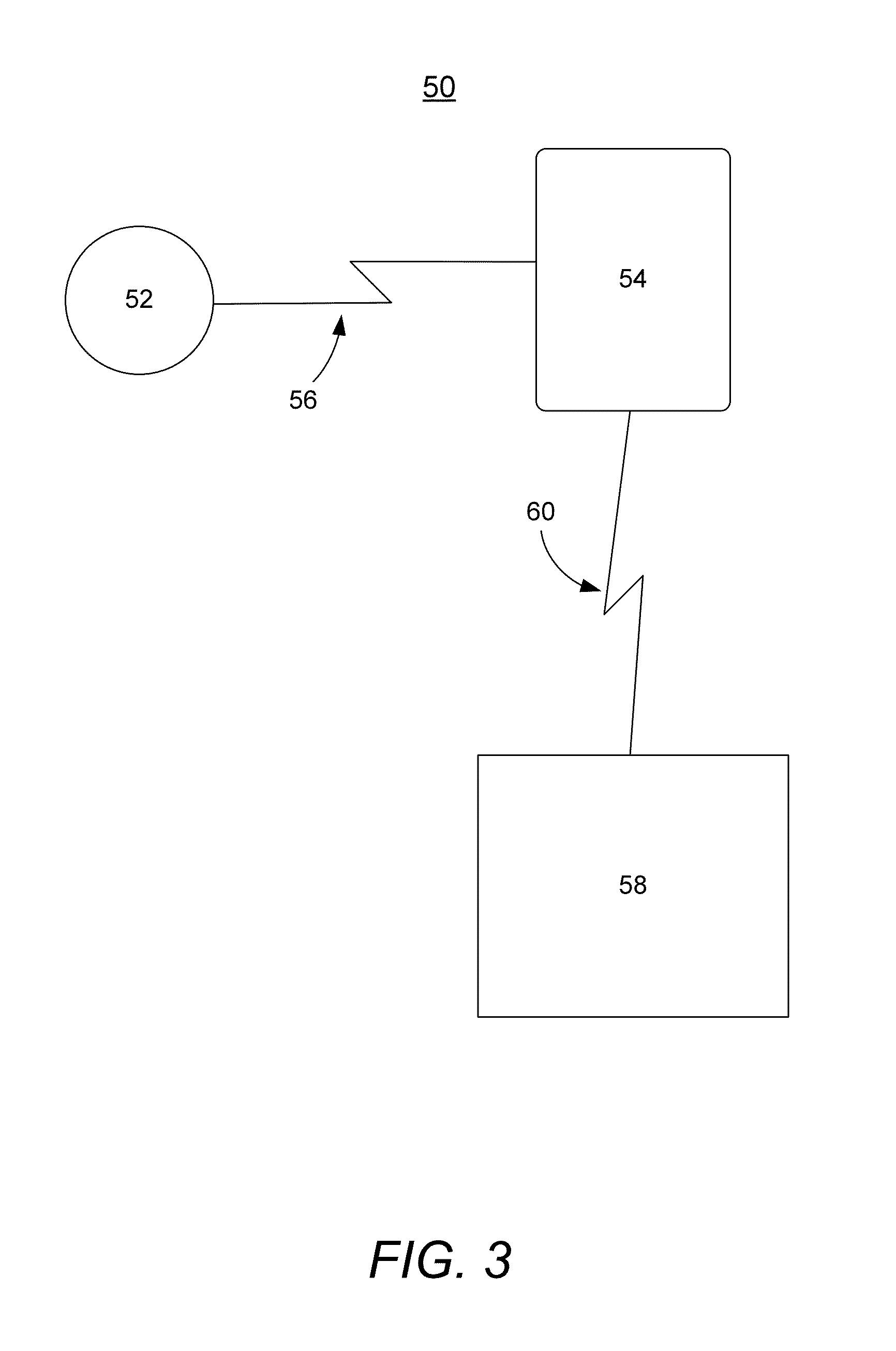
[0041]Embodiments of the invention provide systems, methods, and computer-readable media containing code means for implementing methods for calculating a path of a golf ball on a putting surface and systems, methods, and computer-readable media containing code means for implementing methods for calculating an ideal putt direction and speed to cause a golf ball in an initial location on a putting surface to, when putted, enter a hole in a putting surface. According to embodiments for calculating an ideal putt direction and speed, a method includes computing-device-performed steps of calculating a first plurality of reverse paths lead...


PUM


Abstract

Systems and methods for calculating a path of a golf ball on a putting surface and for calculating an ideal putt direction and speed to cause a golf ball in an initial location on a putting surface to, when putted, enter a hole in a putting surface as described are significantly more computationally efficient and rapid. The efficiency allows implementation of the systems and methods with lower-powered computing devices, including mobile computing devices such as smart phones and the like.

Description

CROSS-REFERENCE TO RELATED APPLICATIONS[0001]This application claims benefit of U.S. Provisional Patent Application No. 62 / 083,013 (Attorney Docket No. 16649.8), filed Nov. 21, 2014, and entitled “Systems and Methods for Determining Optimum Putting Speed and Angle”. This application is a continuation-in-part application of U.S. patent application Ser. No. 14 / 538,129 (Attorney Docket No. 16649.9), filed Nov. 11, 2014, and entitled “Digital Compass Ball Marker”, which is a continuation-in-part application of U.S. patent application Ser. No. 13 / 737,837 (Attorney Docket No. 16649.6), filed Jan. 9, 2013, and entitled “Digital Compass Ball Marker” (now U.S. Pat. No. 8,992,345), which claims the benefit of U.S. Provisional Application No. 61 / 585,122 (Attorney Docket No. 16649.5), filed Jan. 10, 2012, and is entitled “Digital Compass Ball Marker”, and is a continuation-in-part application of U.S. application Ser. No. 12 / 240,086 (Attorney Docket No. 16649.2), filed Sep. 29, 2008, and entitle...

Claims


Application Information

Patent Timeline
Patent Type & Authority Applications(United States)
IPC IPC(8): A63B57/30A63B71/06
CPCA63B71/0619A63B57/353G09B19/0038G06F30/00
Inventor DENNING, ADAMPETERSON, JACK W.
Owner DENNING ADAM
Learn More