Plated tubular lattice structure

a tubular lattice and plating technology, applied in the field of components, can solve the problems of limited structural load of polymeric materials, heavy weight of some weight-sensitive applications,

Active Publication Date: 2016-05-26
RTX CORP
View PDF3 Cites 26 Cited by
  • Summary
  • Abstract
  • Description
  • Claims
  • Application Information

AI Technical Summary

Problems solved by technology
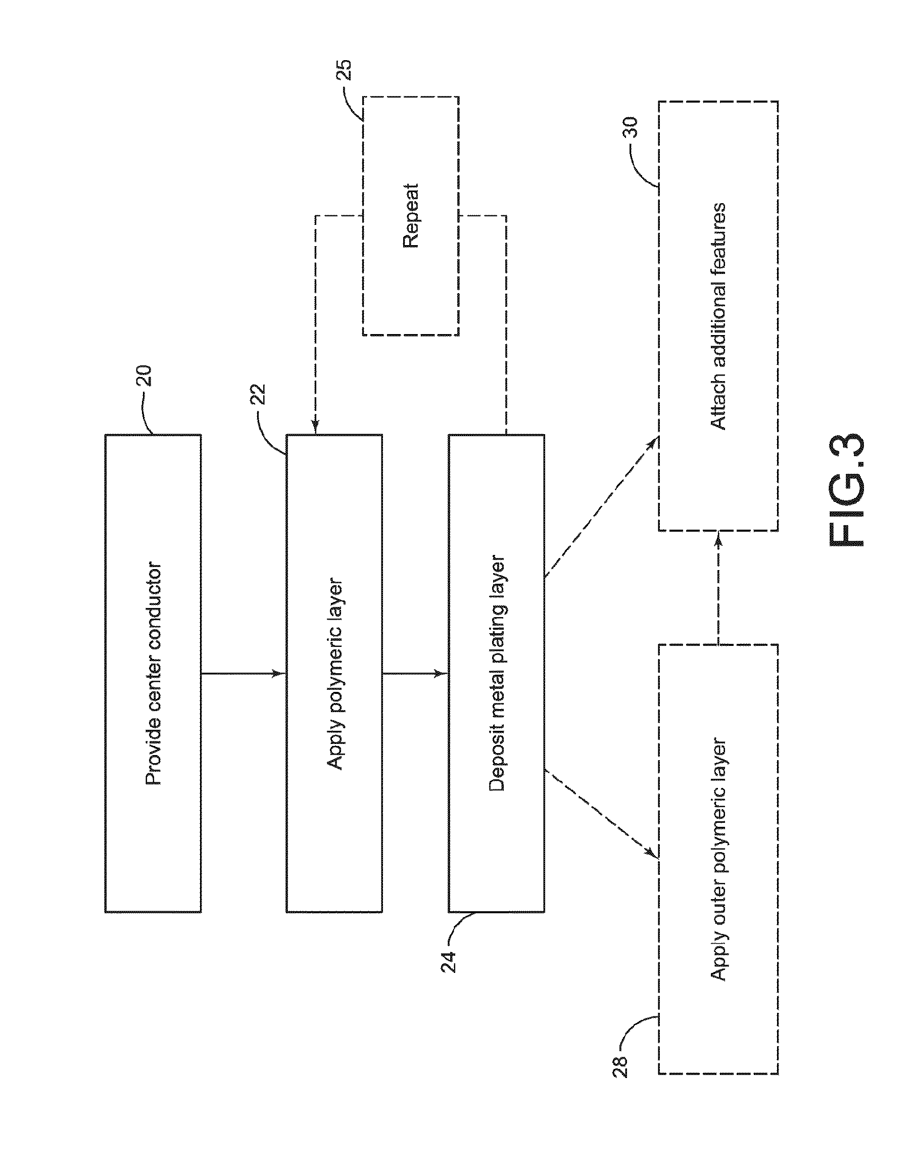
However, parts formed from polymeric materials may be limited to relatively few structurally loaded applications as they are less structurally capable than metallic components of similar geometry.
In contrast, parts formed from metallic materials are strong and less prone to structural failure compared to similarly-dimensioned polymeric parts, but they may be too heavy for some weight-sensitive applications.

Method used


Image

  • Plated tubular lattice structure
  • Plated tubular lattice structure
  • Plated tubular lattice structure

Examples


Embodiment Construction

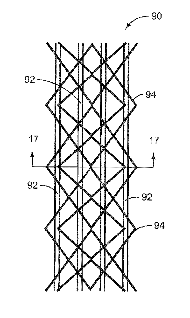
Lightweight Conductor

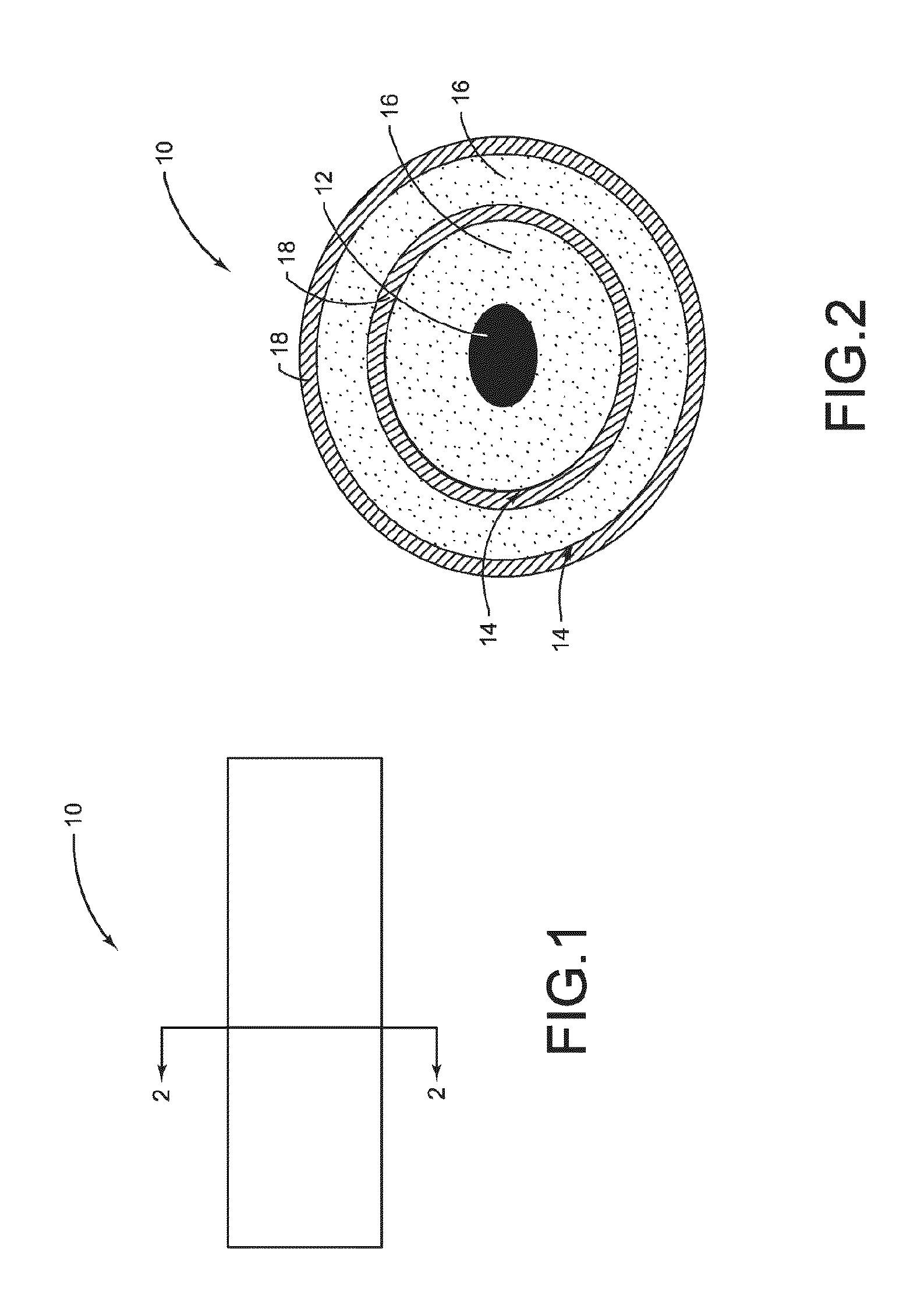
[0081]Electrical cables are involved in transmitting electrical signals between locations to provide power or electrical communication for various applications such as automotive and aerospace applications. The traditional construction of an electrical cable consists of a signal-conducting central core surrounded by a heavy shielding of a conductive material. The central conductor may consist of copper or aluminum and the shielding may consist of copper or a conductive polymer. The shielding layer may shield the central conductor from external electromagnetic noise and may also be involved in signal transmission. Between the central conductor and the shielding layer may be an insulating layer which may insulate the central conductor and the shielding, while also providing mechanical protection to these conductive layers. However, as masses of cables may be bundled and draped around structures in some applications, the heavy shielding employed in standard cable d...


PUM

PropertyMeasurementUnit
thicknessaaaaaaaaaa
thicknessesaaaaaaaaaa

Abstract

A plated tubular lattice structure is described. The plated tubular lattice structure may comprise a backbone structure which may include a plurality of axial posts and a plurality of pyramidal structures extending laterally from the axial posts and connecting the axial posts at nodes. The plated tubular lattice structure may further comprise a metal plating layer plated on an outer surface of the backbone structure.

Description

CROSS-REFERENCE TO RELATED APPLICATIONS[0001]This application claims priority under 35 U.S.C. §119(e) to U.S. Provisional Patent Application Ser. No. 61 / 844,161 filed on Jul. 9, 2013.FIELD OF DISCLOSURE[0002]The present disclosure generally relates to components formed from lightweight and high-strength plated polymers for various applications such as, but not limited to, construction and building material applications. More specifically, the present disclosure relates to the use of plated polymers for the construction of various articles such as, but not limited to, plated tubular lattice structures, cables, containers and packing materials, pipes, fasteners, and brackets.BACKGROUND[0003]Many engineers continue to seek high-strength and lightweight parts for various industrial applications such as, but not limited to, construction, building, and aerospace / automotive applications. Lightweight components may be desirable, for example, in some applications to provide favorable reducti...

Claims


Application Information

Patent Timeline
Patent Type & Authority Applications(United States)
IPC IPC(8): E04B1/30E04B1/19C23C26/00
CPCE04B1/30E04B2001/1927E04B1/19C23C26/00C25D5/022C25D7/04C23C18/1605B29C49/071B29C2949/0715B29B11/06B29B11/14B29C43/183B29C45/14B29K2101/10B29K2101/12B29K2105/20B29K2705/00B29L2009/00B32B15/08B32B2250/02B32B2307/558B32B2605/00
Inventor COOK, GRANT O.ROACH, JAMES T.
Owner RTX CORP
Why Eureka
Try Eureka