
System for diagnosis of robot state

a robot state and robot technology, applied in the field of system and method for diagnosing a robot state, can solve problems such as general inability to communicate with robots, bearings or encoders of robots may fail after a period of time without warning, and not without drawbacks

Active Publication Date: 2016-05-26
FANUC ROBOTICS NORTH AMERICA
View PDF10 Cites 16 Cited by
  • Summary
  • Abstract
  • Description
  • Claims
  • Application Information

AI Technical Summary

Benefits of technology

The present invention is a system and method for collecting and analyzing data from robotic devices in real-time. This allows for proactive maintenance and optimization of the robots. The data is collected from each robot and transferred to a central device for analysis. The analysis is performed by a remote or local analytical and reporting device, which can identify areas of failure or malfunction in the robot. This information is then distributed to at least one recipient. Overall, the invention enables efficient and effective monitoring and management of robotic devices.

Problems solved by technology

Although robots are effective for maximizing efficiency, they are not without drawbacks.
Unlike their human counterparts, robots are generally unable to communicate when they may experience a problem.
For example, bearings or encoders of the robot may fail after a period of time without warning based on variable operating conditions, such as travel distances, temperatures, and load conditions.
However, regularly scheduled intervals may be excessive when operating conditions are less extreme than standard, resulting in components being replaced prematurely, and unnecessarily increasing maintenance costs.
Alternatively, regularly scheduled intervals may be insufficient where operating conditions are more extreme than standard.
In this instance, the robots may experience unexpected problems before the scheduled maintenance period.
Unexpected failures are particularly problematic in the case of high-volume production facilities for a variety of reasons.
In the case of robots, many replacement parts may have long lead times, resulting in extended periods of time that the robot remains inoperable.
Unexpected downtime of a single robot may negatively impact an entire production facility, as manufacturing processes downstream of the inoperable robot may be starved of expected work pieces.
As a result, production may fall behind schedule.

Method used


Image

  • System for diagnosis of robot state
  • System for diagnosis of robot state
  • System for diagnosis of robot state

Examples


Embodiment Construction

[0019]The following detailed description and appended drawings describe and illustrate various embodiments of the invention. The description and drawings serve to enable one skilled in the art to make and use the invention, and are not intended to limit the scope of the invention in any manner.

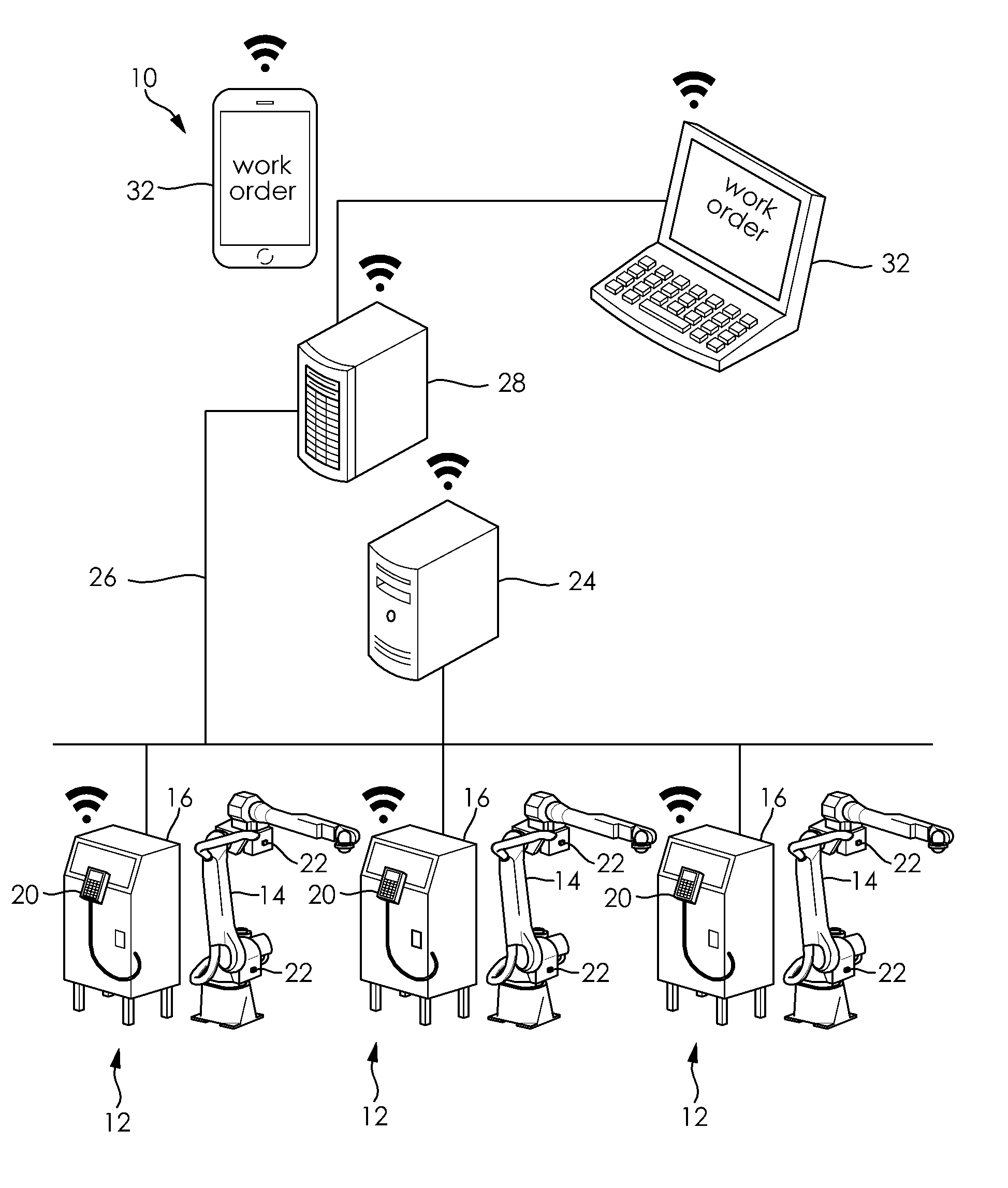
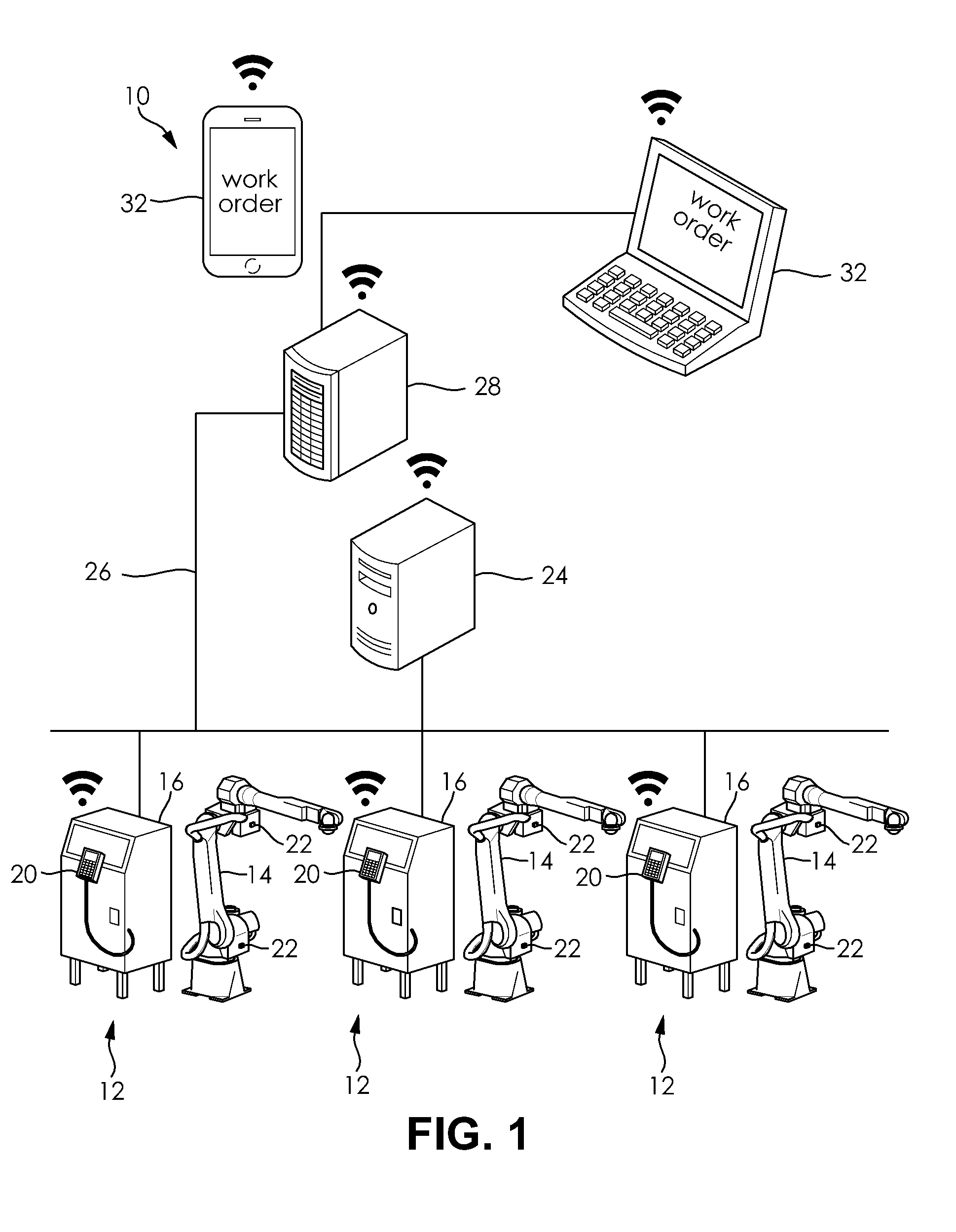
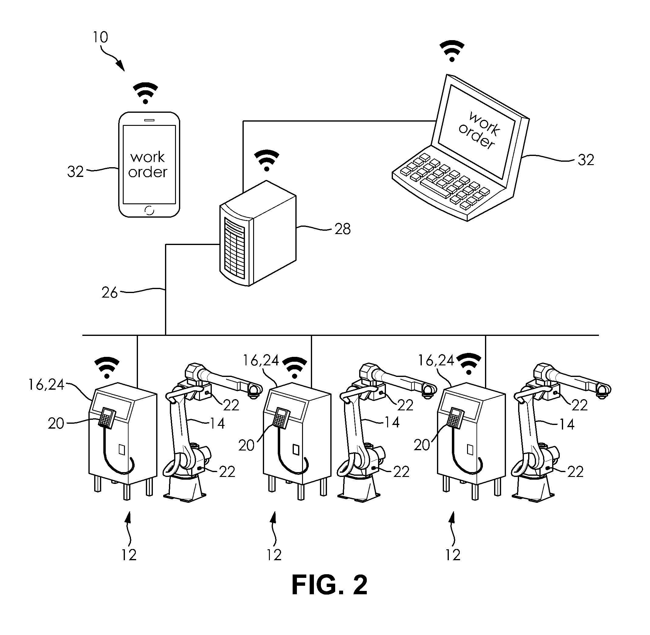
[0020]As shown in FIGS. 1-3, a system 10 for minimizing downtime includes at least one robot 12. In the illustrated embodiment, the system 10 includes a plurality of robots 12. Each of the robots 12 includes a multi-axis robotic arm 14 configured to perform an action on a workpiece, such as cutting, welding, or manipulation, for example.

[0021]The robot 12 includes at least one programmable controller 16 having a memory storage device for storing a plurality of types of data. As used herein, a “controller” is defined as including a computer processor configured to execute software or a software program in the form of instructions stored on the memory storage device. The storage device may be an...


PUM


Abstract

A robot data transfer method includes the step of collecting data from each of a plurality of robots in a multi-robot production facility in real-time. The data collected from the robots is then transferred in real-time from a controller of each of the robots to a first data collection device. Within the first data collection device, the data is buffered using a multi-segment queueing mechanism. The queueing mechanism is configured with a retention policy. The data is then transferred to a second data collection device based on the retention policy of the queueing mechanism of the first data collection device. The second data collection device analyzes the data and determines whether maintenance or optimization is necessary for any of the robots.

Description

CROSS-REFERENCE TO RELATED APPLICATION[0001]This Application claims the benefit of U.S. provisional patent application Ser. No. 62 / 084,899 filed Nov. 26, 2014 hereby incorporated herein by reference in its entirety.FIELD OF THE INVENTION[0002]The invention relates to a system and method for diagnosing a robot state to minimize downtime in a multi-robot production facility.BACKGROUND OF THE INVENTION[0003]Modern manufacturing facilities often utilize a variety of robots to automate production processes. Robots may be arranged in cells, wherein several robots each perform the same process. For example, several robots may all be configured to perform an identical welding process on a work piece. Alternately, several robots may be utilized on an assembly line, wherein each robot performs unique steps of a production sequence.[0004]Although robots are effective for maximizing efficiency, they are not without drawbacks. Unlike their human counterparts, robots are generally unable to commu...

Claims


Application Information

Patent Timeline
IPC IPC(8): H04L29/08H04L12/26
CPCH04L67/06H04L43/06G06Q10/06312G06Q10/0639H04L67/12G05B23/0264H04L67/568
Inventor ECKERT, ISAACGEHEB, GORDONNIEDERQUELL, BRADLEY Q.SUN, YITSAI, JASONWUNDERLICH, RICK E.
Owner FANUC ROBOTICS NORTH AMERICA
Learn More