Hot melt adhesive application method and hot melt adhesive application device
What is AI technical title?
AI technical title is built by Patsnap AI team. It summarizes the technical point description of the patent document.
a technology of adhesive application and hot melt adhesive, which is applied in the direction of coating, combustion types, burners, etc., can solve the problems of waste of a large amount of second fluid and degradation of the work environmen
Active Publication Date: 2016-06-02
SUN TOOL CORP
View PDF1 Cites 0 Cited by
Summary
Abstract
Description
Claims
Application Information
AI Technical Summary
This helps you quickly interpret patents by identifying the three key elements:
Problems solved by technology
Method used
Benefits of technology
Benefits of technology
The invention aims to prevent the scatter of hot-melt adhesive fibers and reduce the amount of energy needed for the pressurized air, while also minimizing the impact on the work environment. This is achieved through the use of pressurized air with improved straight traveling performance that reduces the area affected by melt blow. Additionally, the non-interference space formed between the bottom face of the nozzle and the P zone where the pressurized air comes in contact with the adhesive bead and adhesive filament is formed by melt blowing, further reducing the necessary energy and scatter of adhesive fibers. The invention also allows for more uniform distribution of hot-melt adhesive filaments on the substrate surface.
Problems solved by technology
In each of the inventions in Patent Documents 1 and 2 because the hot-melt fiber or the hot-melt adhesive filament (web) is formed by the melt blowing operation caused by collision or contact of the second fluid (pressurized gas, pressurized air) with the first fluid (hot-melt adhesive bead), there are problems of degradation of the work environment and waste of a large amount of second fluid (pressurized air or the like) due to the scatter of the hot-melt adhesive fiber to the surroundings by a spray effect caused by the contact of the second fluid (pressurized air or the like) with the first fluid (hot-melt adhesive bead).
Method used
Image
Click on the blue label to locate the original text in one second.
Reading with bidirectional positioning of images and text.
Examples
first embodiment
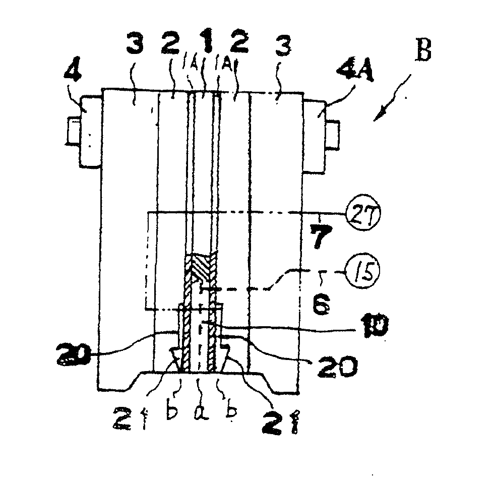
[0069]With reference to FIGS. 5 to 7, an application nozzle device A is formed by disposing pressurized air plates 2, 2 and cover plates 3, 3 on front and back opposite sides of an adhesive plate 1 in a traveling direction of an application line.
[0070]The plates 3, 2, 1, 2, and 3 are fixed and integrated with each other by fastening members 4, 4A.
[0071]Each of adhesive holes 10 communicates with an adhesive feed port 14 through communication paths 11, 12, and 13 and communicates with a hot-melt feed source 15.
[0072]Left and right pressurized air holes 20 are integrated with each other through a communication path 23 and communicate with a pressurized air feed port 26 through communication paths 24 and 25.
[0073]Pressurized air is fed from a pressurized air feed source 27 to the pressurized air feed port 26.
[0074]The large number of adhesive holes 10 are formed in the adhesive plate 1 to form a large number of adhesive hole openings a in a bottom face of a nozzle in a line orthogonal ...
second embodiment
[0087]With reference to FIG. 10 to FIG. 12, an application nozzle device A is formed by disposing pressurized air plates 2, 2 and cover plates 3, 3 on front and back opposite sides of an adhesive plate 1 in a traveling direction of an application line with adhesive plate 1 at a center.
[0088]The plates 3, 2, 1, 2, and 3 are fixed and integrated with each other by fastening members 4, 4A.
[0089]Each of adhesive holes 10 communicates with an adhesive feed port 14 through communication paths 11, 12, and 13 and communicates with a hot-melt feed source 15.
[0090]Left and right pressurized air holes 20 are integrated with each other through a communication path 23 and communicate with a pressurized air feed port 26 through communication paths 24 and 25.
[0091]Pressurized air is fed from a pressurized air feed source 27 to the pressurized air feed port 26.
[0092]The large number of adhesive holes 10 are formed in the adhesive plate 1 to form a large number of adhesive hole openings a in a botto...
PUM
Abstract
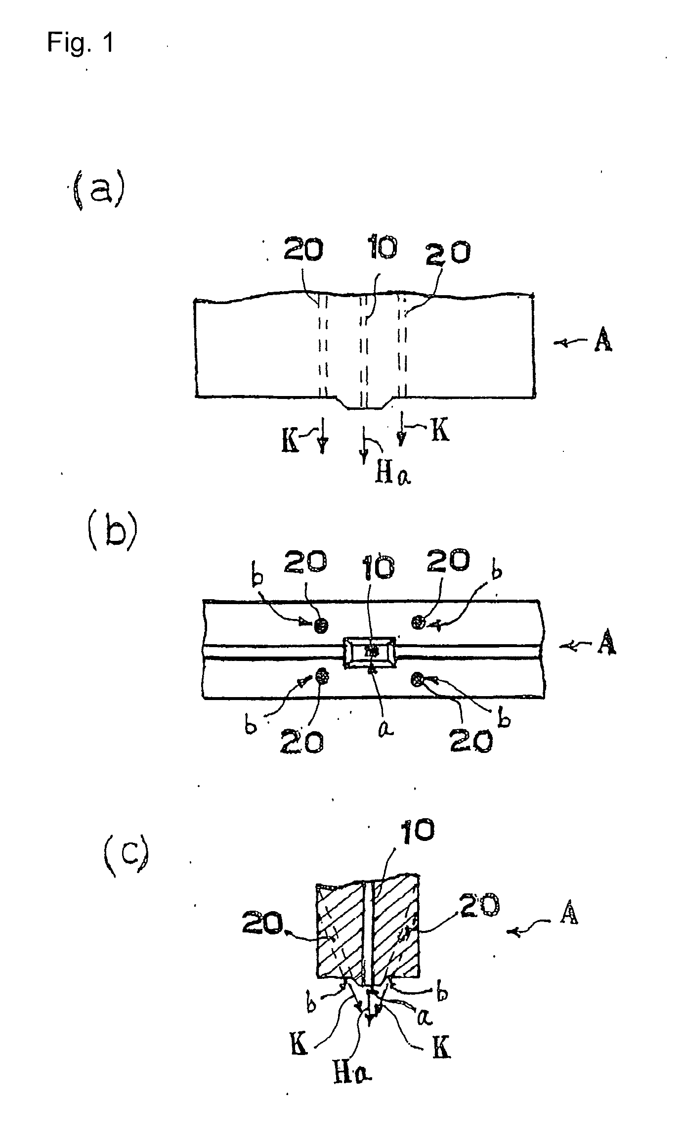
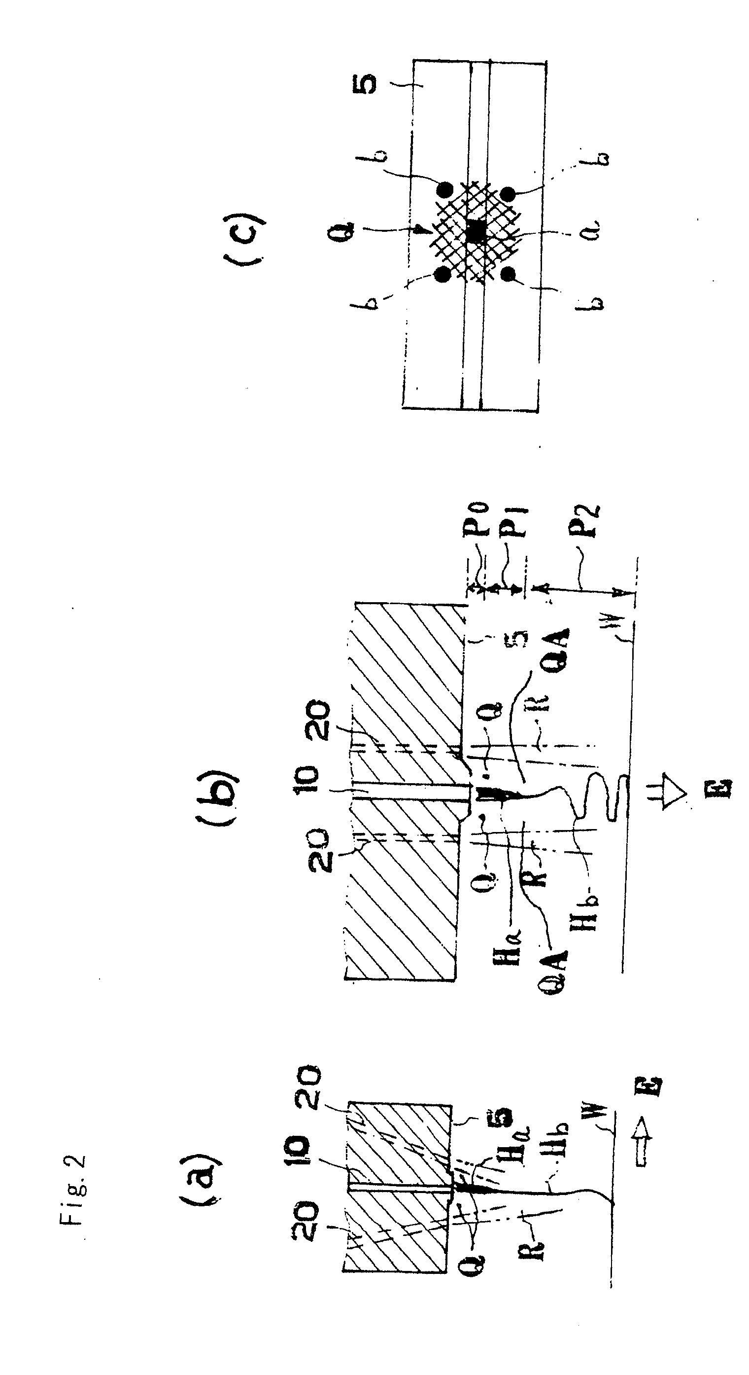
In front view of the application nozzle, all of the pressurized air flow K and adhesive flow H are made to run parallel to each other in the vertical direction.Of the pressurized air flows K from the pressurized air hole b in the pressurized air plate, the two that are located on one side of the adhesive hole opening a and from a pair in the front-to-back direction are tilted so as to approach each other.The extension lines thereof are located on the side of the adhesive bead, which results from the adhesive flow discharged from the adhesive hole opening, and have directions that converge.The respective pressurized air flows on the two side of the adhesive bead are made to flow downward while uniting in the direction of convergence.A web in which the adhesive bead is elongated while being swung in the transverse direction is formed and, near the bottom surface of the application nozzle, a non-interference space Q is formed between the adhesive bead and the fore pressurized air flow.The adhesive bead, resulting from the adhesive flow discharged from the adhesive hole opening, and the pressurized air flows do not interfere with each other and walls R of pressurized air flows are formed below the non-interference space Q and on either side of the adhesive bead.
Description
TECHNICAL FIELD[0001]The invention of the present application relates to a hot-melt adhesive application method and a hot-melt adhesive application device for forming an adhesive applied face on an upper face of a substrate on a traveling application line while forming fibrous beads of hot-melt adhesive by causing pressurized air from pressurized air holes to act on the hot-melt adhesive beads from hot-melt adhesive holes.BACKGROUND ART[0002]With regard to the hot-melt adhesive application method for applying adhesive in a predetermined pattern on an upper face of a substrate on a traveling application line while forming fibrous beads of hot-melt adhesive by causing pressurized air from pressurized air holes to act on the hot-melt adhesive beads from hot-melt adhesive holes, the following inventions are known.[0003]Patent Document 1: “Application Nozzle Device in Curtain Fiber-Like Spray Application Device” in Unexamined Japanese Patent Publication No. H08-243461 (Japanese Patent No...
Claims
Application Information
Patent Timeline
Application Date:The date an application was filed.
Publication Date:The date a patent or application was officially published.
First Publication Date:The earliest publication date of a patent with the same application number.
Issue Date:Publication date of the patent grant document.
PCT Entry Date:The Entry date of PCT National Phase.
Estimated Expiry Date:The statutory expiry date of a patent right according to the Patent Law, and it is the longest term of protection that the patent right can achieve without the termination of the patent right due to other reasons(Term extension factor has been taken into account ).
Invalid Date:Actual expiry date is based on effective date or publication date of legal transaction data of invalid patent.
Patent Type & AuthorityApplications(United States)

