Display device and electronic apparatus

a display device and electronic technology, applied in the direction of mechanical pattern conversion, identification means, instruments, etc., can solve the problems of deteriorating the usability of operating electronic devices for health people, affecting the usability of electronic devices such as smartphones which include a touch-panel display device, and practicably being unable to perceive which part of the touch-panel is to be touched to make an effective input or know, etc., to achieve the effect of reducing the space for resonance, reducing the oscillation of the entir

Active Publication Date: 2016-06-02
TIANMA MICRO ELECTRONICS CO LTD
View PDF6 Cites 14 Cited by
  • Summary
  • Abstract
  • Description
  • Claims
  • Application Information

AI Technical Summary

Benefits of technology

[0015]The following analysis has been made by the present inventors. As depicted in Patent Document 1 or Non-Patent Document 1 mentioned above, there is an existing technique which assists operations through: providing a supporting substrate, electrodes joined to the supporting substrate, and an insulating film covering the electrodes; and laminating a visual sense display with a tactual sense presenting panel structured to present a tactual sense to a user by an electrostatic force generated between the electrodes and the user by a voltage signal applied to the electrodes from outside, thereby allowing the user to perceive a tactual sense with a finger.
[0021]It is therefore an exemplary object of the present invention to provide a display device and an electronic apparatus capable of improving the ambience by mutual effects of a visual sense and a tactual sense or capable of assisting operations through presenting a sense of texture to the skin of the human beings effectively while suppressing generation of unpleasant noises.
[0023]As described above, the present invention is designed as a structure in which the resin exhibiting transparency for visible light rays is filled between the tactual sense presenting unit and the visual sense display unit. Thus, as an exemplary advantage according to the invention, it is possible to suppress oscillation of the entire surface of the tactual sense presenting panel when mechanical oscillation generated by deformation of the finger is transmitted to the larger-area tactual sense presenting panel and to eliminate the space for causing resonance without spoiling both display on the screen and presentation of the tactual sense.
[0024]This makes it possible to provide the display device and the electronic apparatus exhibiting such excellent feature that it is possible to improve the ambience by mutual effects of a visual sense and a tactual sense or to assist operations through presenting a sense of texture to the skin of the human beings effectively while suppressing generation of unpleasant noises.

Problems solved by technology

However, the surface of the display device with a touch panel is evenly hard, so that same tactual senses are felt by touching any of the sections displayed on the screen.
Thus, it is practically impossible to perceive which part of the touch panel is to be touched to make an effective input or to know whether or not an effective input is done without relying on a visual sense (without looking at the panel).
This causes such an issue that the electronic apparatuses such as smartphones which include a touch-panel display device cannot be used by those with impaired vision.
Furthermore, the fact that those electronic apparatuses cannot be operated without relying on the visual sense results in deteriorating the usability for operating the electronic apparatuses for health people.
Especially, a large number of electrodes are embedded to give a sense of texture to a large number of sections, so that complicated wirings are required.
Changing the positions and the number of sections where a sense of texture is presented according to the displayed object requires rearrangement of the electrodes, so that it is practically impossible.

Method used


Image

  • Display device and electronic apparatus
  • Display device and electronic apparatus
  • Display device and electronic apparatus

Examples


first exemplary embodiment

Modification of First Exemplary Embodiment

[0129]FIG. 3E is an explanatory chart showing the structures of a display device 150 according to a modification of the first exemplary embodiment of the present invention. Further, FIG. 3F is an explanatory chart showing a sectional-view structure of the display device 150 shown in FIG. 3E.

[0130]The display device 150 has many points in common with that of the first exemplary embodiment, so that mainly the different points will be described. In the display device 100 according to the first exemplary embodiment, the resin is filled in the entire display region of the visual sense display unit. However, in the display device 150, as shown in FIGS. 3E and 3F, a resin 160 is filled only in a part of the region where the visual sense display unit 10 and the tactual sense presenting unit 20 face with each other. More specifically, the resin 160 is filled in the vicinity of the centers of each of the visual sense display unit 10 and the tactual se...

second exemplary embodiment

[0132]In a second exemplary embodiment of the present invention, the chassis is omitted from the structure of the first exemplary embodiment of the present invention described above. Instead, an adhesive tape 240 is constituted with a resin exhibiting transparency for visible light rays.

The same effects as those of the first exemplary embodiment of the present invention can also be acquired with this structure. Further, this structure is suited for decreasing the thickness of the apparatus by reducing the number of components. Hereinafter, this will be described in more details.

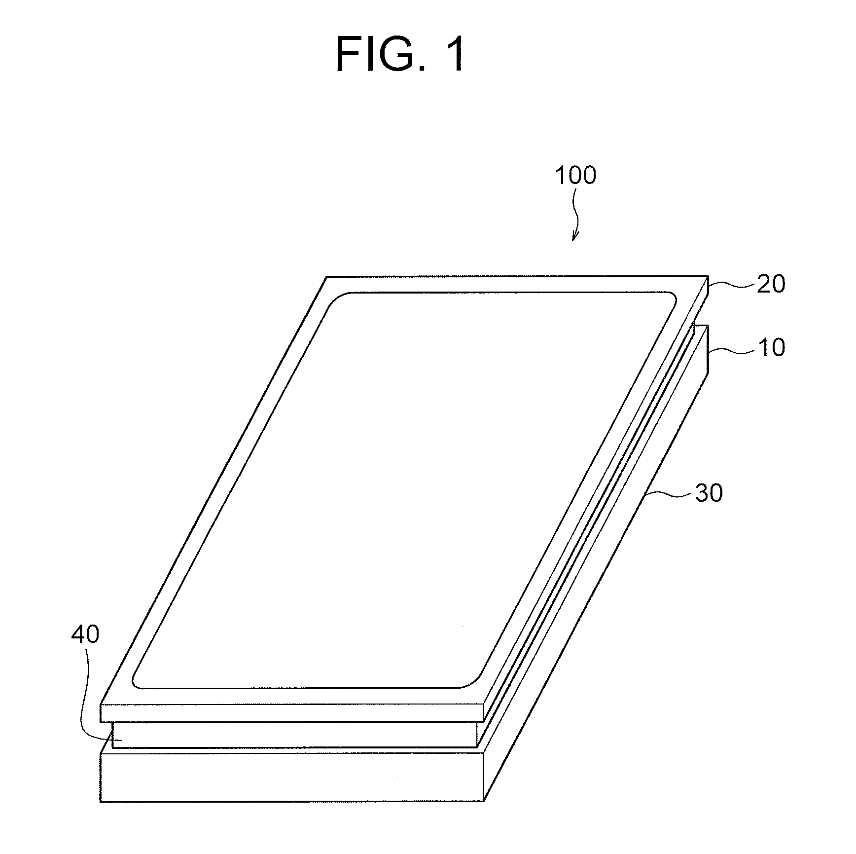
[0133]FIG. 4 is a perspective view showing the structures of a display device 200 according to the second exemplary embodiment of the present invention. The display device 200 is structured by stacking the visual sense display unit 10 and the tactual sense presenting unit 20 same as each of those of the first exemplary embodiment. The touch coordinate detection unit 11 which is also same as that of the first ...

third exemplary embodiment

[0141]In addition to the structures of the first and second exemplary embodiments of the present invention described above, a third exemplary embodiment of the present invention employs a structure in which a resin 340 filled between the visual sense display unit 10 and the tactual sense presenting unit 20 is set to have a higher elasticity modulus (Young's modulus) in a fringe part 341 than the elasticity modulus in a center part 342. Further, the resin 340 is a curable resin, and the curing rate in the fringe part 341 is higher than the curing rate in the center part 342.

With this structure, the same effects as those of the first and second exemplary embodiments of the present invention can be acquired and the oscillation absorbing property can be improved further. Hereinafter, this will be described in more details.

[0142]FIG. 6 is a perspective view showing structures of a display device 300 according to the third exemplary embodiment of the present invention. Further, FIG. 7 is ...


PUM


Abstract

To provide a display device and the like capable of assisting operations by effectively presenting a sense of texture to the skin of human beings while suppressing generation of unpleasant noises. The display device includes: a visual sense display unit which displays an operation screen to be a target of touch operations done by a user by image signals supplied from outside; and a plate-type tactual sense presenting unit which is disposed on the upper side of the visual sense display unit and presents a tactual sense that can be perceived by the user on the operation screen. The tactual sense presenting unit includes X-electrodes and Y-electrodes which exhibit transparency for visible light rays and operate by voltage signals supplied from outside, and a resin exhibiting transparency for visible light rays is filled in a layered-state gap between the visual sense display unit and the tactual sense presenting unit.

Description

CROSS-REFERENCE TO RELATED APPLICATION[0001]This application is based upon and claims the benefit of priority from Japanese patent application No. 2014-243550, filed on Dec. 1, 2014, the disclosure of which is incorporated herein in its entirety by reference.BACKGROUND OF THE INVENTION[0002]1. Field of the Invention[0003]The present invention relates to a display device and an electronic apparatus. More specifically, the present invention relates to a display device and the like capable of assisting operations by effectively presenting a sense of texture to the skin of human beings.[0004]2. Description of the Related Art[0005]Conventionally, a display device on which a touch panel with which input can be done by fingers is loaded contributes to achieving user-friendly interactive operability by being mounted to a system that controls the display content and the apparatus actions according to the input. Thus, electronic apparatuses to which a touch panel is mounted such as smartphone...

Claims


Application Information

Patent Timeline
Patent Type & Authority Applications(United States)
IPC IPC(8): G06F3/01G06F3/041G06F3/047
CPCG06F3/016G06F3/047G06F3/0416G06F3/0414G06F3/0412G09F9/00G06F3/04166G06F3/042
Inventor HAGA, HIROSHINAKANISHI, FUTOSHIIKEDA, NAOYASU
Owner TIANMA MICRO ELECTRONICS CO LTD
Why Eureka
Try Eureka