Aerial device with quick-coupling implement

a technology of implements and aerial devices, which is applied in the field of aerial devices and their implements, can solve the problems of difficult decoupling of implements of prior art, difficult to achieve, and difficult to couple the aerial devices of the prior art, and achieves the effects of easy manipulation, and quick and easy coupling of implements

Active Publication Date: 2016-06-09
ALTEC INDS
View PDF31 Cites 5 Cited by
  • Summary
  • Abstract
  • Description
  • Claims
  • Application Information

AI Technical Summary

Benefits of technology

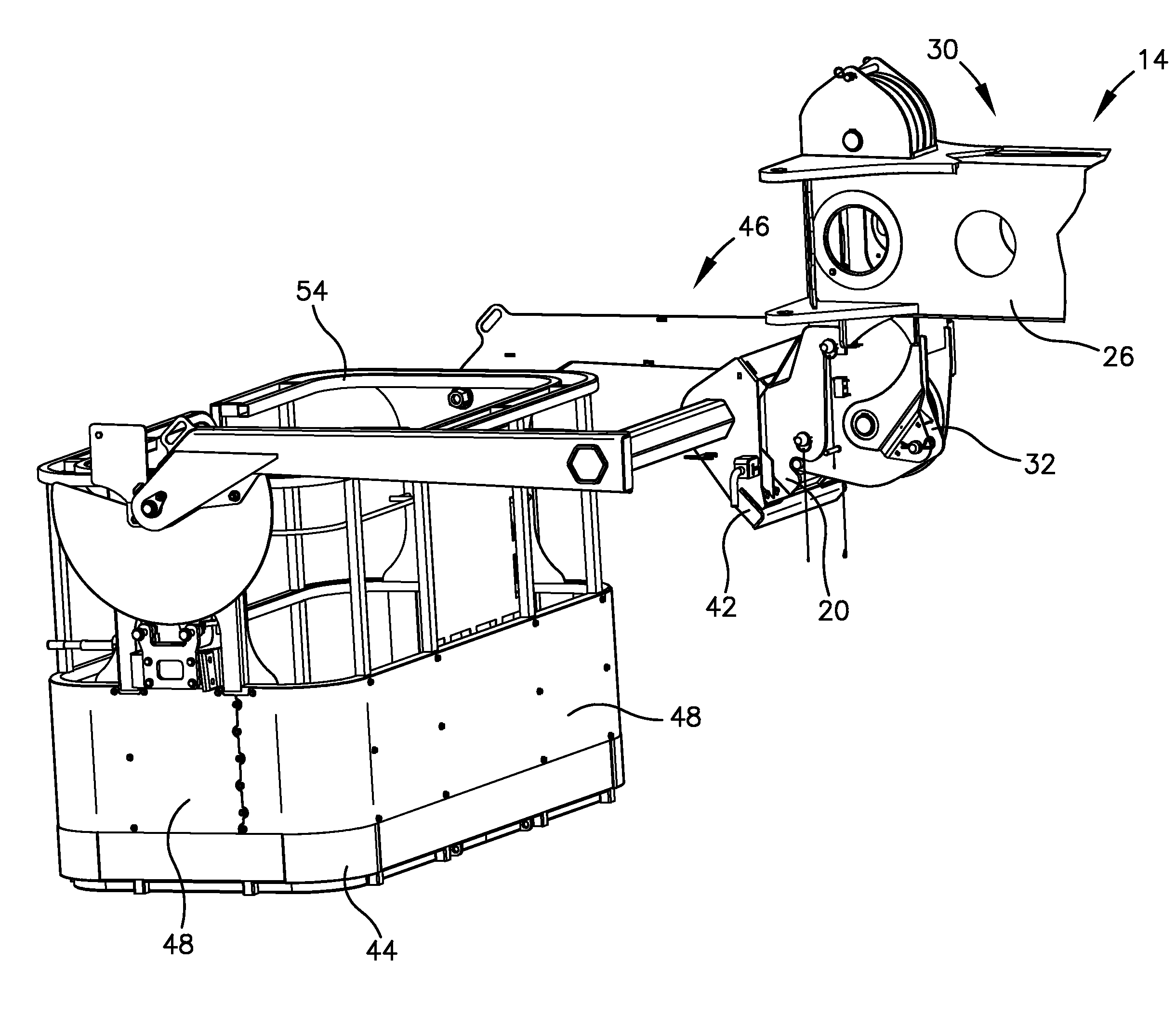
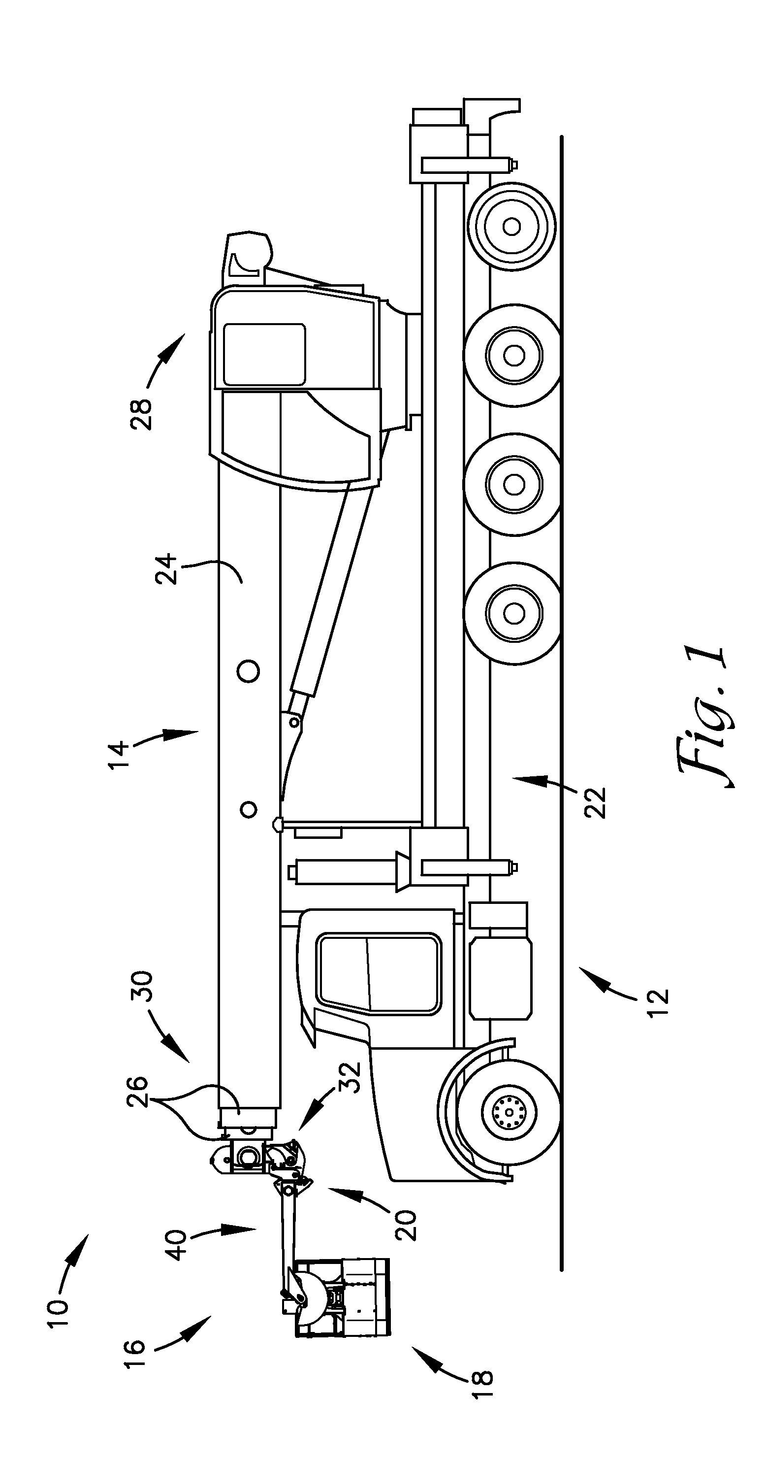
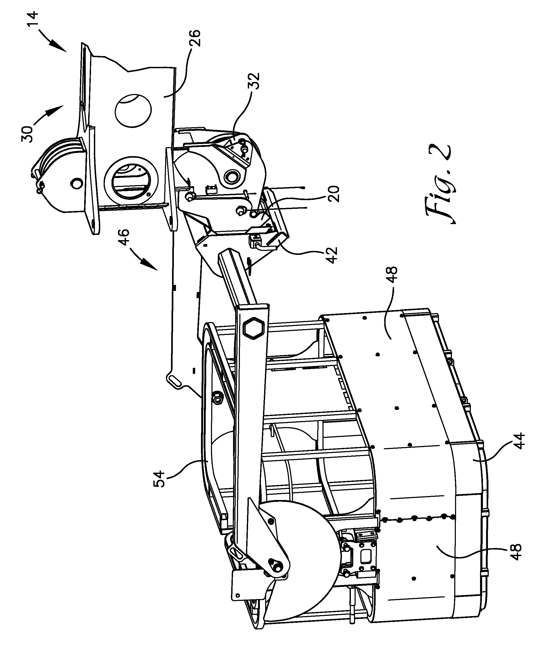
[0006]Embodiments of the invention solve the above-mentioned problems by providing an adapter for quick coupling. The adapter is secured by a utility worker to a boom raise of an aerial device. The adapter can then quickly and easily couple to an implement, such as a utility platform assembly, an auger, a winch, etc. The precise alignment of the openings allows for easy use of the adapter, which is relatively lighter and easier to manipulate, instead of the implement itself. The adapter presents hook segments for ease of installation of one of the pins, as discussed below. The adapter, once installed, allows for quick and easy coupling of the implement without requiring precise alignment of the adapter and the implement. Moreover, the boom raise and the implement need not be level with each other. Alternatively stated, the adapter, when positioned on the boom raise, can interface with the platform at a plurality of angles, thus not requiring the precise positioning of the boom raise and implement of the prior art. The utility worker decouples the implement by operating at least one latch, which can be easily done by the utility worker even if there is weight on the pins because the pins do not have to be removed to decouple the implement.

Problems solved by technology

Utility platforms and other implements of the prior art are difficult to couple to the aerial device.
This is difficult to achieve because the utility platform can be very heavy and because the boom assembly cannot make precise movements.
This is also difficult because the alignment must be precise for the pin to fit into the openings and because the utility worker is often using both hands to align the implement with the openings of the boom raise.
Similarly, decoupling the implements of the prior art is difficult.
Accordingly, an aerial device, a utility platform assembly, and a method for quickly coupling an implement to the aerial device are lacking in the prior art.

Method used


Image

  • Aerial device with quick-coupling implement
  • Aerial device with quick-coupling implement
  • Aerial device with quick-coupling implement

Examples


Embodiment Construction

[0026]The following detailed description references the accompanying drawings that illustrate specific embodiments in which the invention can be practiced. The embodiments are intended to describe aspects of the invention in sufficient detail to enable those skilled in the art to practice the invention. Other embodiments can be utilized and changes can be made without departing from the scope of the invention. The following detailed description is, therefore, not to be taken in a limiting sense. The scope of the invention is defined only by the appended claims, along with the full scope of equivalents to which such claims are entitled.

[0027]In this description, references to “one embodiment,”“an embodiment,” or “embodiments” mean that the feature or features being referred to are included in at least one embodiment of the technology. Separate references to “one embodiment,”“an embodiment,” or “embodiments” in this description do not necessarily refer to the same embodiment and are a...


PUM


Abstract

A quick coupling implement for an aerial device has a base, a boom assembly, the implement, and an adapter. The adapter is emplaced on a portion of the boom assembly to allow for quickly coupling the implement. The adapter comprises a boom-raise-interfacing segment with at least one opening for securing to the boom raise of the boom assembly via a retaining pin. The adapter also comprises an implement-interfacing segment that presents a complementary shape to an adapter-receptor segment of the implement. The implement may be a utility platform for supporting a utility worker.

Description

BACKGROUND[0001]1. Field[0002]Embodiments of the invention relate to aerial devices and their implements. More specifically, embodiments of the invention relate to an aerial device that is adapted to quickly couple to and decouple from an implement, such as a utility platform assembly, via an adapter.[0003]2. Related Art[0004]Utility workers utilize an aerial device to perform numerous tasks. For example, the aerial device may be equipped with a utility platform to reach an inaccessible location, equipped with an auger to drill a hole, or equipped with a winch or other tool to move a heavy object. Because the utility worker must perform numerous different tasks, it is occasionally necessary for the utility worker to change the implement. Also, the utility worker may remove the implement before traveling to or from a worksite, performing maintenance, etc.[0005]Utility platforms and other implements of the prior art are difficult to couple to the aerial device. The utility worker coup...

Claims


Application Information

Patent Timeline
Patent Type & Authority Applications(United States)
IPC IPC(8): F16M11/04F16M11/20B66F11/04F16M11/38
CPCF16M11/041B66F11/044F16M11/2092F16M11/38B66F11/046
Inventor MILES, JOHNSON X.STAKOR, GREGORY M.
Owner ALTEC INDS
Why Eureka
Try Eureka