Transmission Arrangement Such as for Energy and/or Signal Transmission

Active Publication Date: 2016-06-09
SMW AUTOBLOK SPANNSYST GMBH
View PDF11 Cites 8 Cited by
  • Summary
  • Abstract
  • Description
  • Claims
  • Application Information

AI Technical Summary

Benefits of technology

[0004]It is therefore a task of the present invention to provide a transmission arrangement such as for energy and/or signal transmission, optionally for use in a machining center, respectively a turning and/or milling center which enables best possible freedom of movement when machining the tool. The transmission arrangement should be optionally suitable for transmitting energy and/or signals between rotary components of a machining center. Optionally, the transmission

Problems solved by technology

Apart from plug connections, sliding contacts are also known for rotary chucks which are, however, subject to heavy wear and tear due to their functioning principle.
A conne

Method used


Image

  • Transmission Arrangement Such as for Energy and/or Signal Transmission
  • Transmission Arrangement Such as for Energy and/or Signal Transmission
  • Transmission Arrangement Such as for Energy and/or Signal Transmission

Examples


Embodiment Construction

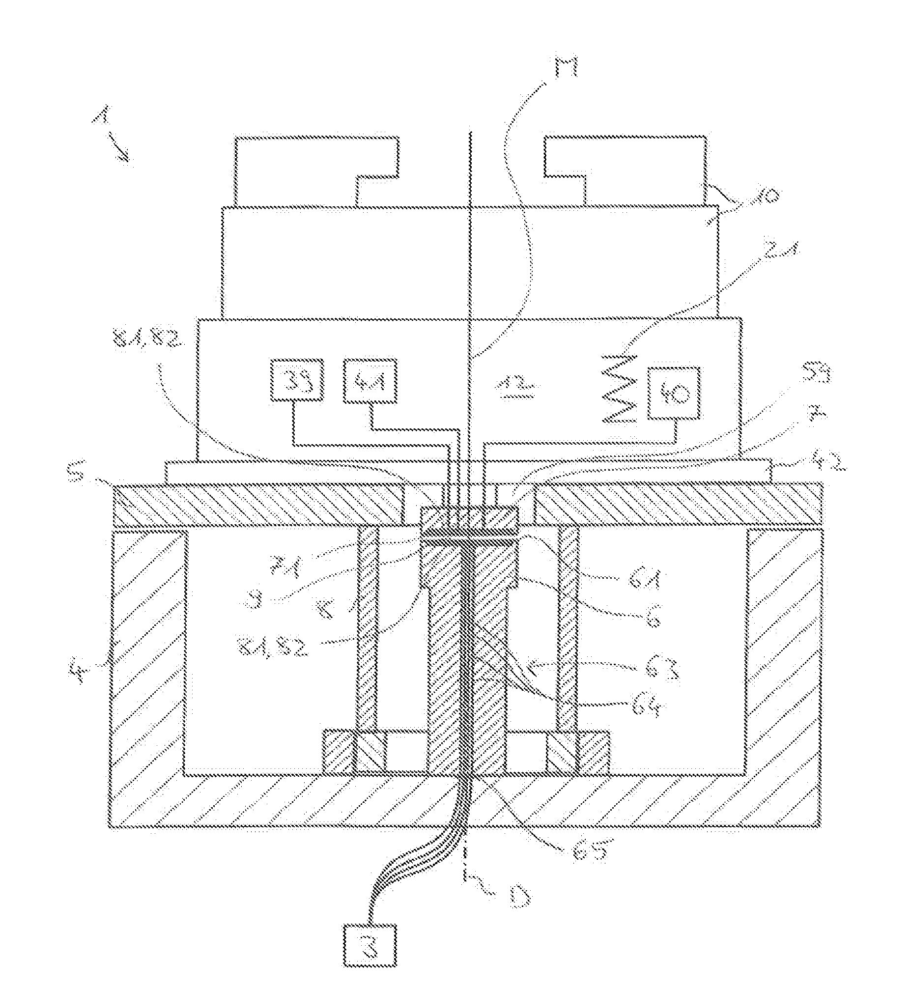
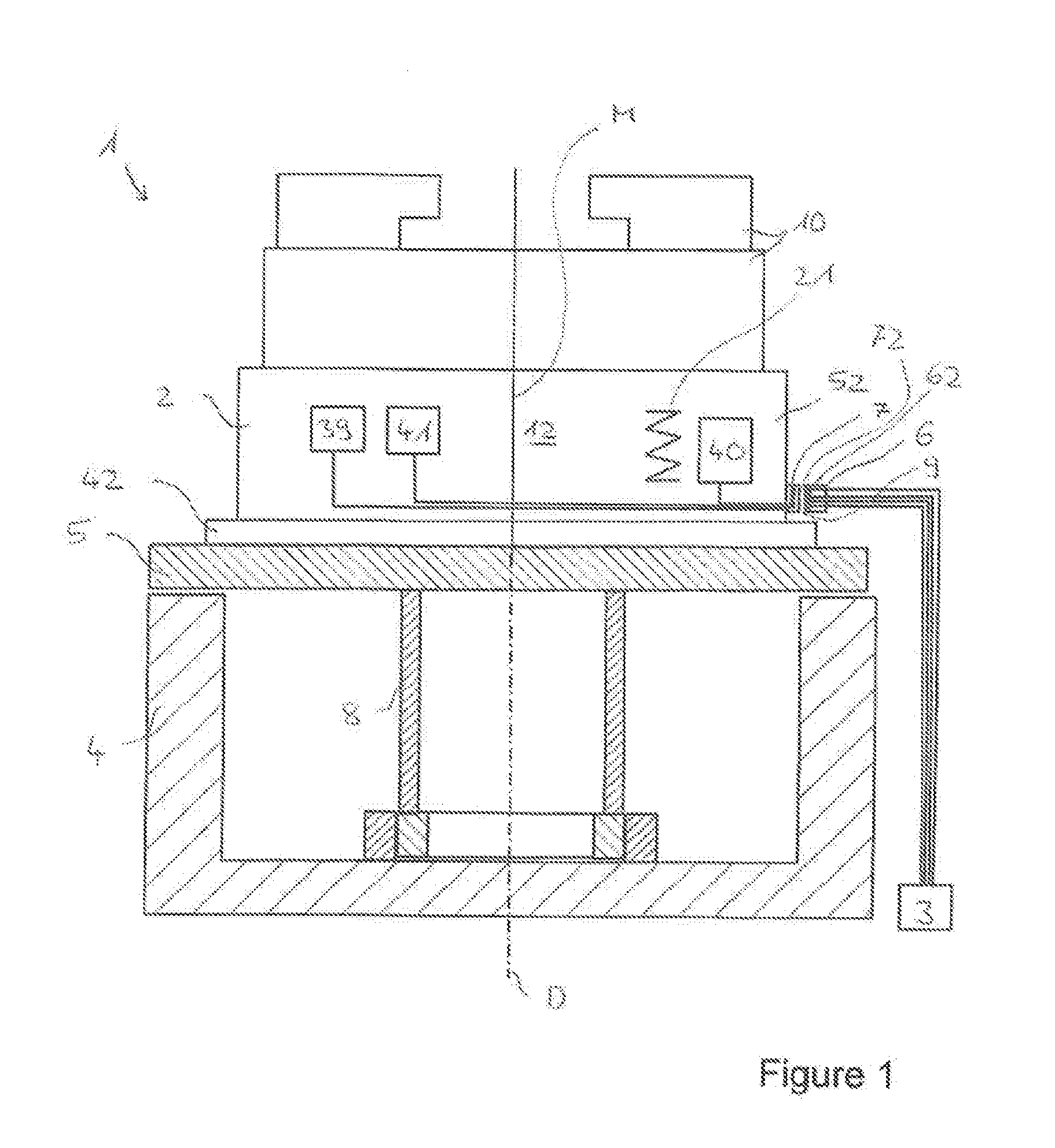
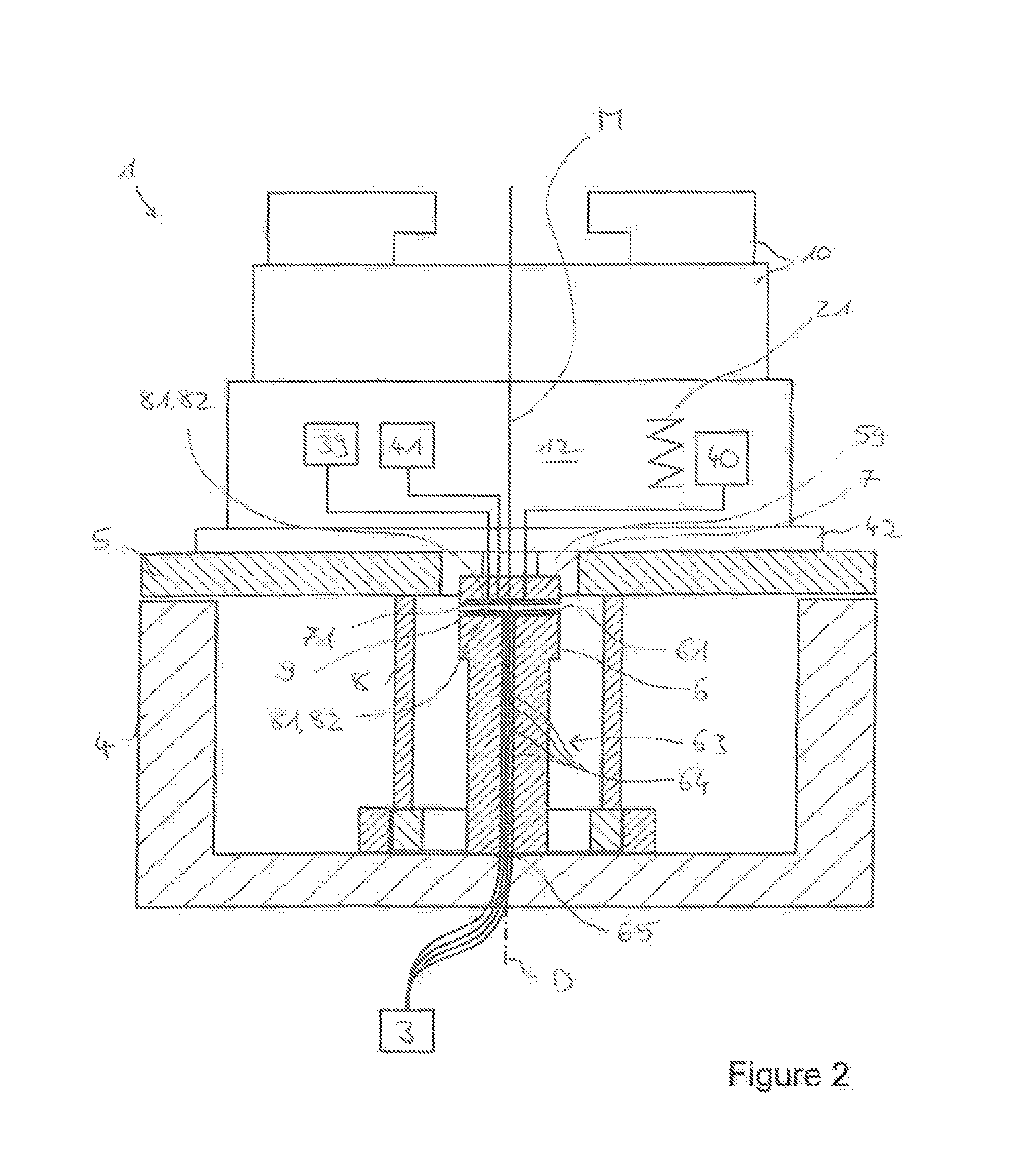
[0074]FIGS. 1-4 each show an embodiment of the inventive transmission arrangement in a schematic representation, with the configuration and arrangement of the first and second transmission devices 6, 7 each being different in FIGS. 1-4. An inventive transmission arrangement 1 comprises a clamping unit 2, a console 4, in which a rotary table 5 is rotatably mounted, as well as a first transmission device 6 and a second transmission device 7. Further details for the optional implementation of the clamping unit 2 will be explained below in conjunction with FIGS. 6, 7 and 8. Here, the clamping unit 2 is implemented as an understructure cylinder which is releasably fastened on the surface of a rotary table 5 by a fastening flange 42, for example via screw connections or via several intermediate columns configured with suitable adapter elements for releasably fastening the fastening flange 42 to the rotary table 5. The rotary table 5 rotates, respectively turns relative to the console 4 wh...


PUM


Abstract

A transmission arrangement such as for energy and/or signal transmission, optionally for use in a machining center, respectively a turning and/or milling center, comprising a clamping unit comprising an outer housing of a preferably cylindrical basic shape, an inner housing received within the outer housing, as well as an inner cylinder held within the inner housing to be adjustable in an actuating direction A, said inner cylinder being configured to transmit a compressive or tensile force for clamping purposes, wherein the inner housing is supported against the outer housing via springs, and is displaceably mounted in the actuating direction A with respect to the outer housing and thus forms a spring force storage, wherein an electric motor is arranged integrated within the clamping unit to apply force in the actuating direction A to the inner cylinder via intermediate gear means, a console having a rotary table mounted therein to be rotatable, at least one first transmission device connected to the console and at least one second transmission device connected to the clamping unit, wherein the clamping unit is releasably fastened on the rotary table, and first and second transmission devices are configured to transmit electrical energy for driving the electric motor in a non-contact, preferably inductive manner between a first transmission device and a second transmission device.

Description

CROSS-REFERENCE TO RELATED PATENT APPLICATIONS[0001]This application claims the benefit of priority to European Application No. 14196366.0, filed on Dec. 4, 2014, which is hereby incorporated by reference in its entirety.BACKGROUND[0002]The invention relates to a transmission arrangement such as for energy and / or signal transmission, optionally for use in a machining center, respectively a turning and / or milling center, wherein the transmission arrangement comprises a clamping unit, a console having a rotary table rotatably supported therein, and first and second transmission means according to the features of claim 1 or 2.[0003]In the machining center, workpieces and tools are moved relative to each other in order to machine a workpiece clamped on the machine table. Connecting a clamping means, including a chuck for clamping a tool or a workpiece to a power supply or a machine control unit via a plug connection is known from the prior art. Apart from plug connections, sliding conta...

Claims


Application Information

Patent Timeline
IPC IPC(8): H02J5/00H04B5/00H02J7/02H02J7/04B23Q1/00G01P3/00
CPCH02J5/005B23Q1/0009H04B5/0037H02J7/025H02J7/042G01P3/00B23B31/16045B23B31/28B23Q1/522Y10T279/27
Inventor MAURER, ECKHARD
Owner SMW AUTOBLOK SPANNSYST GMBH
Why Eureka
Try Eureka