Lighting device control system for light adaptation

Inactive Publication Date: 2016-06-09
IDSYS
View PDF2 Cites 8 Cited by
  • Summary
  • Abstract
  • Description
  • Claims
  • Application Information

AI Technical Summary

Benefits of technology

[0013]In the present invention, it may be possible to reduce eye fatigue of the user because the b

Problems solved by technology

However, the above-mentioned conventional lighting device may cause inconvenience of the user because the brightness of the lighting device is gradually reduced to the predetermined brightness after turning on at a maximum brightness upon sensing the user.
That is, when the user moves from one place to another place in an indoor space where

Method used


Image

  • Lighting device control system for light adaptation
  • Lighting device control system for light adaptation
  • Lighting device control system for light adaptation

Examples


Embodiment Construction

[0101]Various embodiments have been described in the best mode for carrying out the invention.

INDUSTRIAL APPLICABILITY

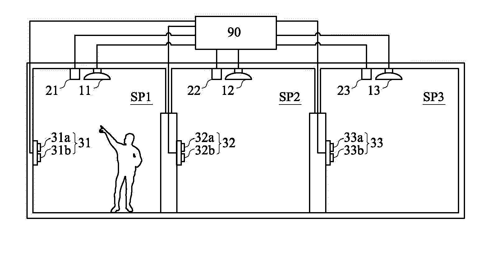
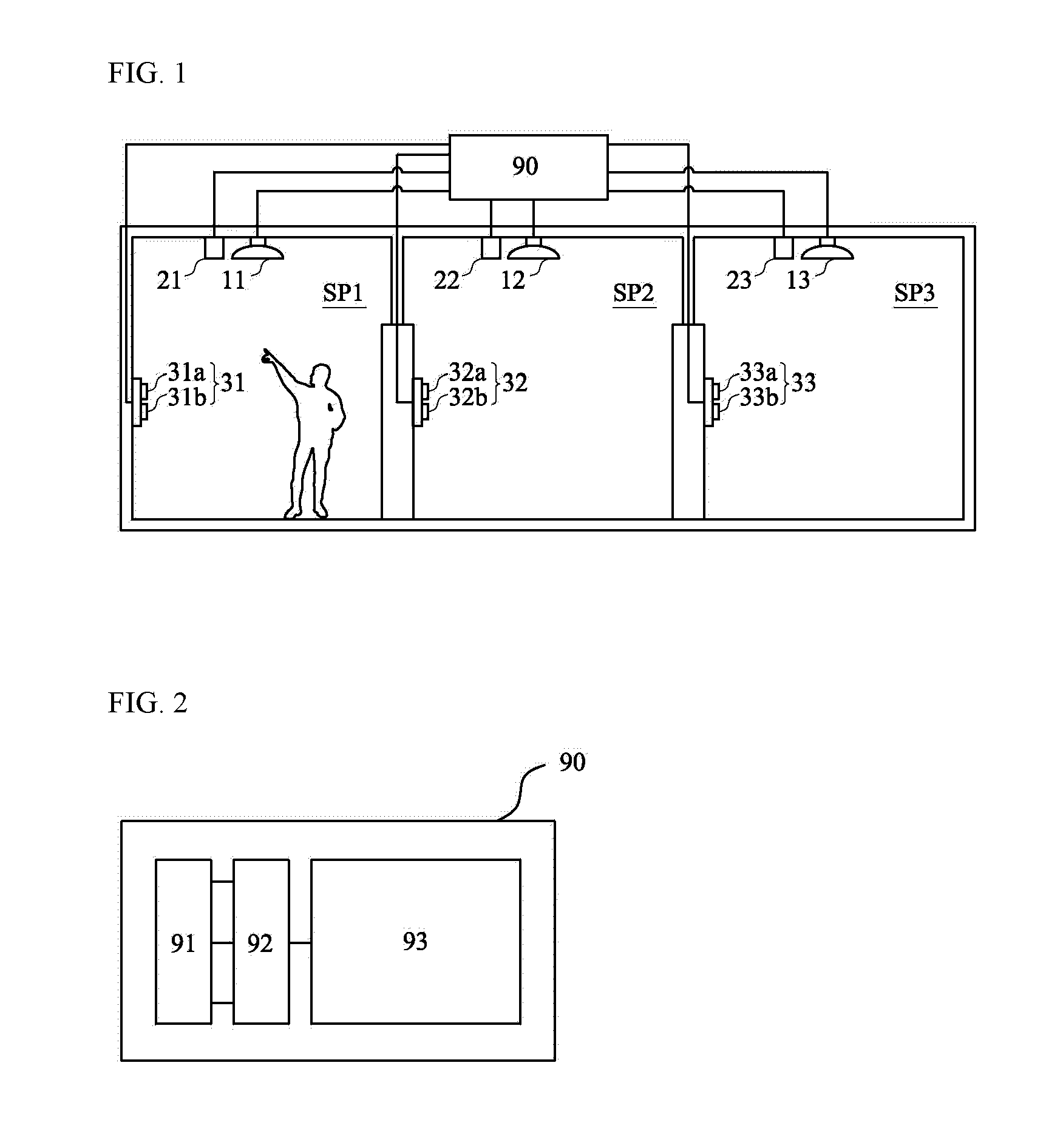
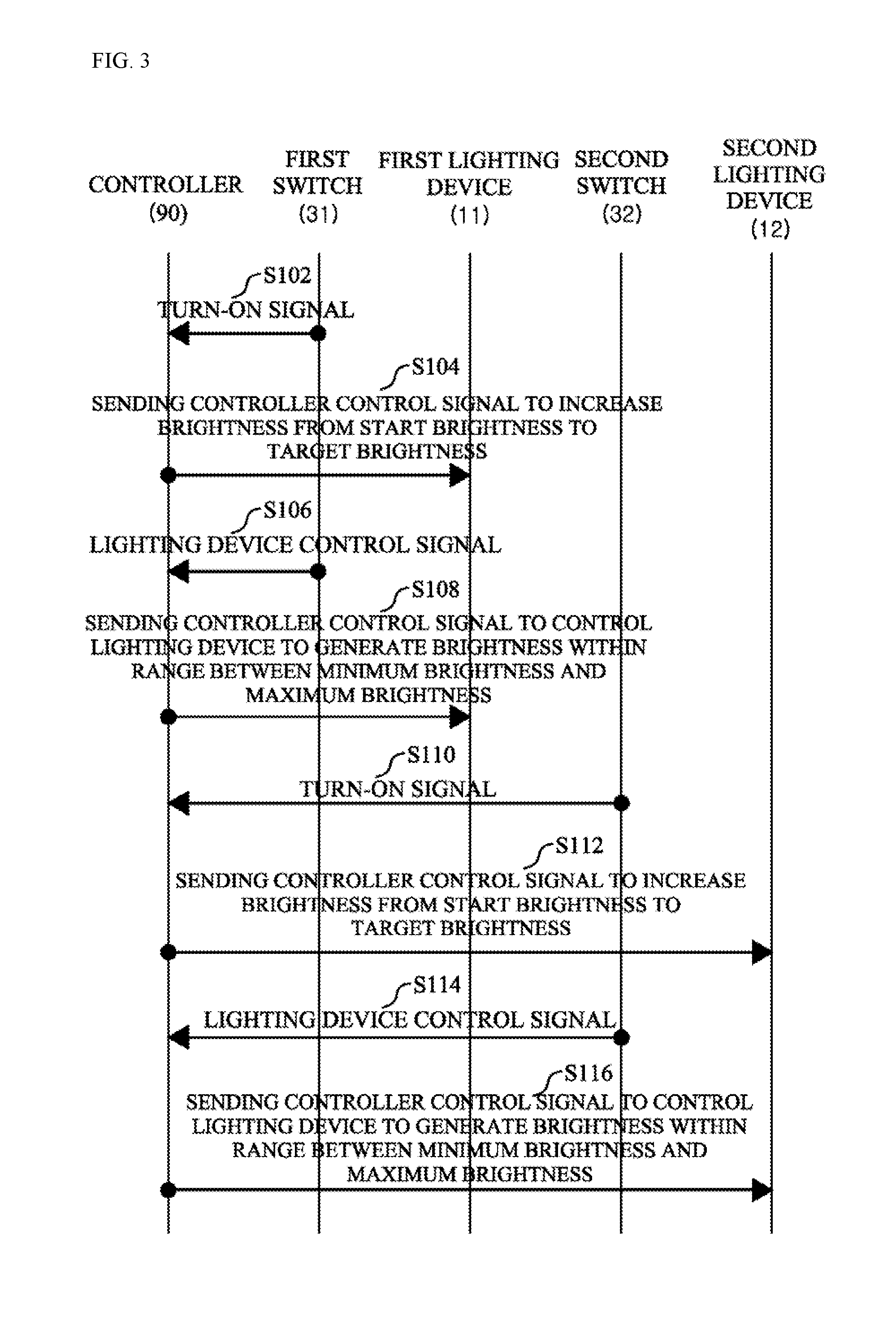
[0102]Consequently, in the present invention, when the user moves from one space to another space, the lighting device installed in the latter space gradually brightens after turning on at a brightness corresponding to the illuminance of the former space, for light adaptation illumination.

[0103]Those skilled in the art to which the present invention pertains can appreciate that the invention may be embodied in other specific forms without changing the technical spirit or essential characteristics. Therefore, the embodiments described above should be understood as exemplary rather than limiting in all aspects. The scope of the present invention should also be interpreted by the claims below rather than the foregoing description. The meaning and range of the claims and all modifications as would he derived from the equivalent concept intended to be included within the ...


PUM


Abstract

The invention relates to a control system. In particular, the invention has an object to provide a lighting device control system for controlling a lighting device upon receiving a turn-on signal to turn on the lighting device, to emit light capable of generating an illuminance equal to or lower than an ambient illuminance around a place where the lighting device is installed.

Description

TECHNICAL FIELD[0001]The present invention relates to an illumination control system, and more particularly to a light adaptation lighting device control system for controlling a lighting device configured to allow a person to easily adapt to brightness.BACKGROUND ART[0002]Lighting devices are installed in various spaces of the interior of an office, a hallway, a stairway, an entrance, a living room, a bedroom, and the like.[0003]Conventional lighting devices are configured to be simply turned on or off by a switch.[0004]However, recently developed lighting devices are provided with a sensor capable of sensing movement of the user or the like, for the purpose of achieving energy savings, etc. Such a lighting device has functions of turning on upon sensing movement of the user, and turning off when no movement is sensed.[0005]However, a non-lighting state, namely, a dark state, is kept until the sensor of the lighting device senses the user because the lighting device is turned on or...

Claims


Application Information

Patent Timeline
IPC IPC(8): H05B37/02
CPCH05B37/0245H05B37/0218H05B47/11H05B47/18Y02B20/40F21V23/0464H05B47/175
Inventor YOON, YOENG CHEOL
Owner IDSYS
Why Eureka
Try Eureka