Compression paddle for use in breast imaging

a compression paddle and breast imaging technology, applied in the field of breast imaging, can solve the problems of discomfort for patients, applicability, and various detriments of compression paddles, and achieve the effect of lowering the compression paddl

Active Publication Date: 2016-06-16
GENERAL ELECTRIC CO
View PDF4 Cites 19 Cited by
  • Summary
  • Abstract
  • Description
  • Claims
  • Application Information

AI Technical Summary

Problems solved by technology

Such approaches, however, may suffer from various detriments.
However, such compression can be uncomfortable for the patient.

Method used


Image

  • Compression paddle for use in breast imaging
  • Compression paddle for use in breast imaging
  • Compression paddle for use in breast imaging

Examples


Embodiment Construction

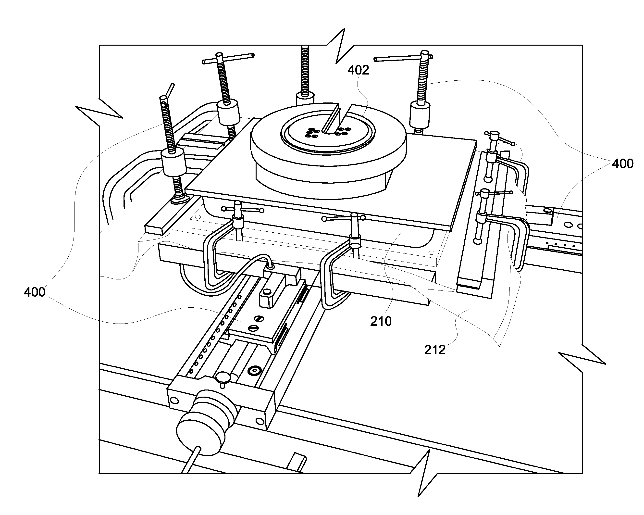
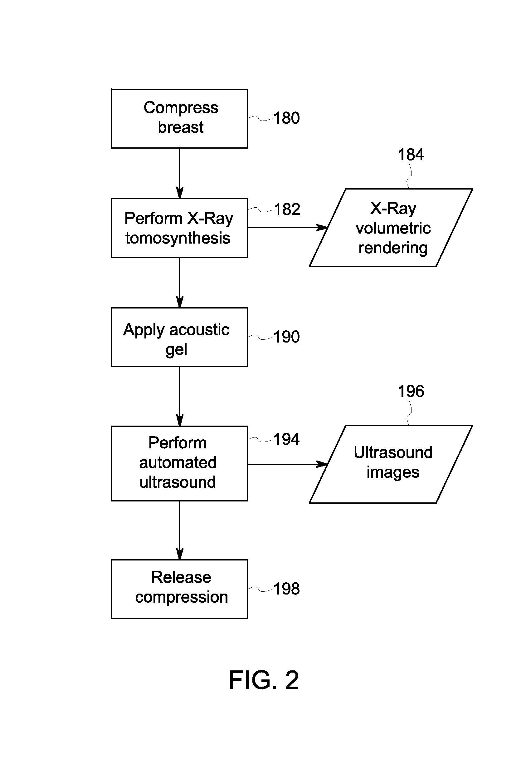
[0021]The present approach is directed towards acquisition of breast image data, such as the acquisition of ultrasound image data. For example, in certain embodiments, an imaging system may be used to implement a pre-programmed scan protocol in an automated manner. Such scan protocols may involve compression of the breast tissue but, in certain embodiments, such compression need not involve compressing the breast tissue to uniform thickness (i.e., the compression may be tapered or angled so as to accommodate the patient anatomy. Further in some embodiments, the compression paddles employed may be at least partly conformable.

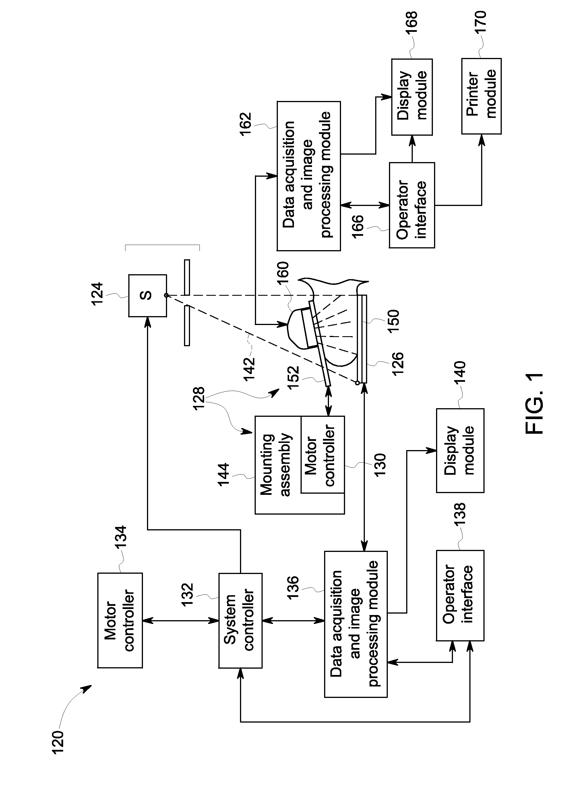
[0022]In certain embodiments discussed herein, the compression paddle may be used in conjunction with a suitable imaging modality or combination of modalities, such as ultrasound and / or tomosynthesis. In certain examples discussed herein, the compression paddles may be described in use with a combined tomosynthesis / ultrasound imaging system, with a tomosynthesis ...


PUM

PropertyMeasurementUnit
tensionaaaaaaaaaa
tensionsaaaaaaaaaa
forceaaaaaaaaaa

Abstract

The present disclosure relates to the manufacture and use of a non-rigid breast compression paddle, such as a compression paddle having a mesh material forming the primary interface with patient tissue. In certain implementations, an automatic feedback driven approach may be used in conjunction with such a compression paddle for compressing breast tissue.

Description

BACKGROUND[0001]The present approach relates generally to the field of breast imaging and, more specifically, to compression paddles for use in acquiring breast images.[0002]In modern healthcare facilities, non-invasive imaging approaches are used for identifying, diagnosing, and treating diseases. One purpose to which such techniques are applied is the acquisition of mammographic images for use in identifying and diagnosing lesions or irregularities in the breast tissue.[0003]In conventional approaches, breast imaging or mammography may be implemented using radiographic techniques, such as by projecting X-rays through the breast tissue and reconstructing images based on the differential transmission of the X-rays through the tissue. Such approaches, however, may suffer from various detriments. For example, in such approaches the breast tissue is typically compressed to a substantially uniform thickness so that the X-rays, at all points of interest, are traversing roughly the same t...

Claims


Application Information

Patent Timeline
Patent Type & Authority Applications(United States)
IPC IPC(8): A61B6/04A61B6/00
CPCA61B6/502A61B6/0414A61B6/025A61B6/4417A61B8/4281A61B8/4416
Inventor DAVIS, CYNTHIA ELIZABETH LANDBERGZHANG, ZHIPENGGRIFFIN, WESTON BLAINEMAO, YING
Owner GENERAL ELECTRIC CO
Why Eureka
Try Eureka