
Method and control unit for setting at least one parameter of a driver assistance device of a vehicle

a technology of driver assistance and control unit, which is applied in the direction of vehicle components, signalling/lighting devices, optical signalling, etc., can solve the problems of increasing the visual range by turning up the headlights to be too small, and achieve the effect of reducing the perceived image contrast, avoiding discomfort, and avoiding discomfor

Active Publication Date: 2016-06-16
ROBERT BOSCH GMBH
View PDF2 Cites 5 Cited by
  • Summary
  • Abstract
  • Description
  • Claims
  • Application Information

AI Technical Summary

Benefits of technology

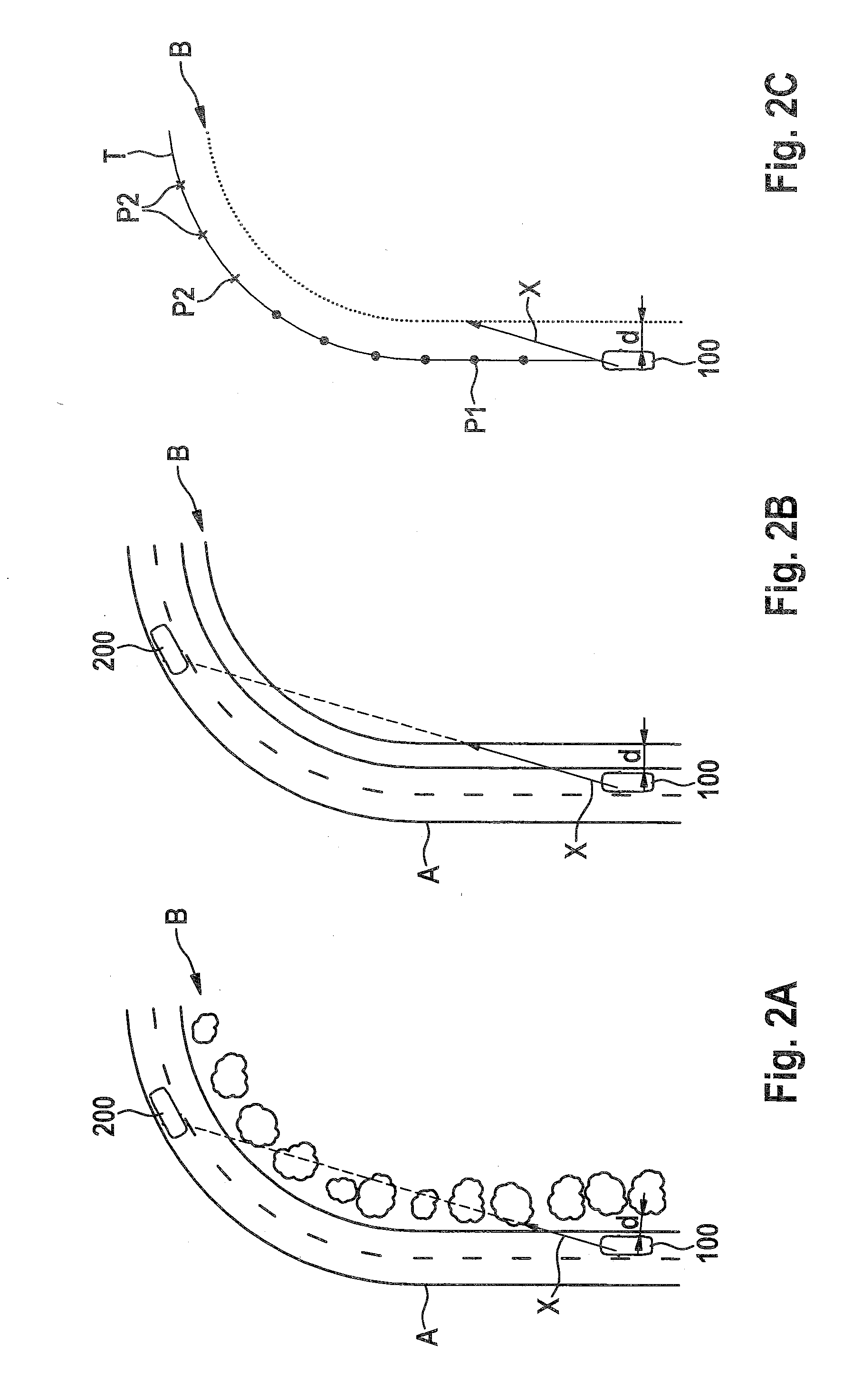
The present invention improves safety and comfort for drivers by using sensor-based assistance systems. These systems can adapt to changing conditions to provide better visibility and a larger visual range for the driver. For example, it can detect and respond to the presence of concealment objects, such as vegetation or buildings, in the roadway to optimize the brightness and distribution of the vehicle's headlights. High beam assists can also use information about the surrounding conditions, such as road illumination or vehicle traffic, to adapt the system's response and provide better visibility and a larger visual range for the driver. These systems prevent flickering sensations and provide a more comfortable and safe driving experience.

Problems solved by technology

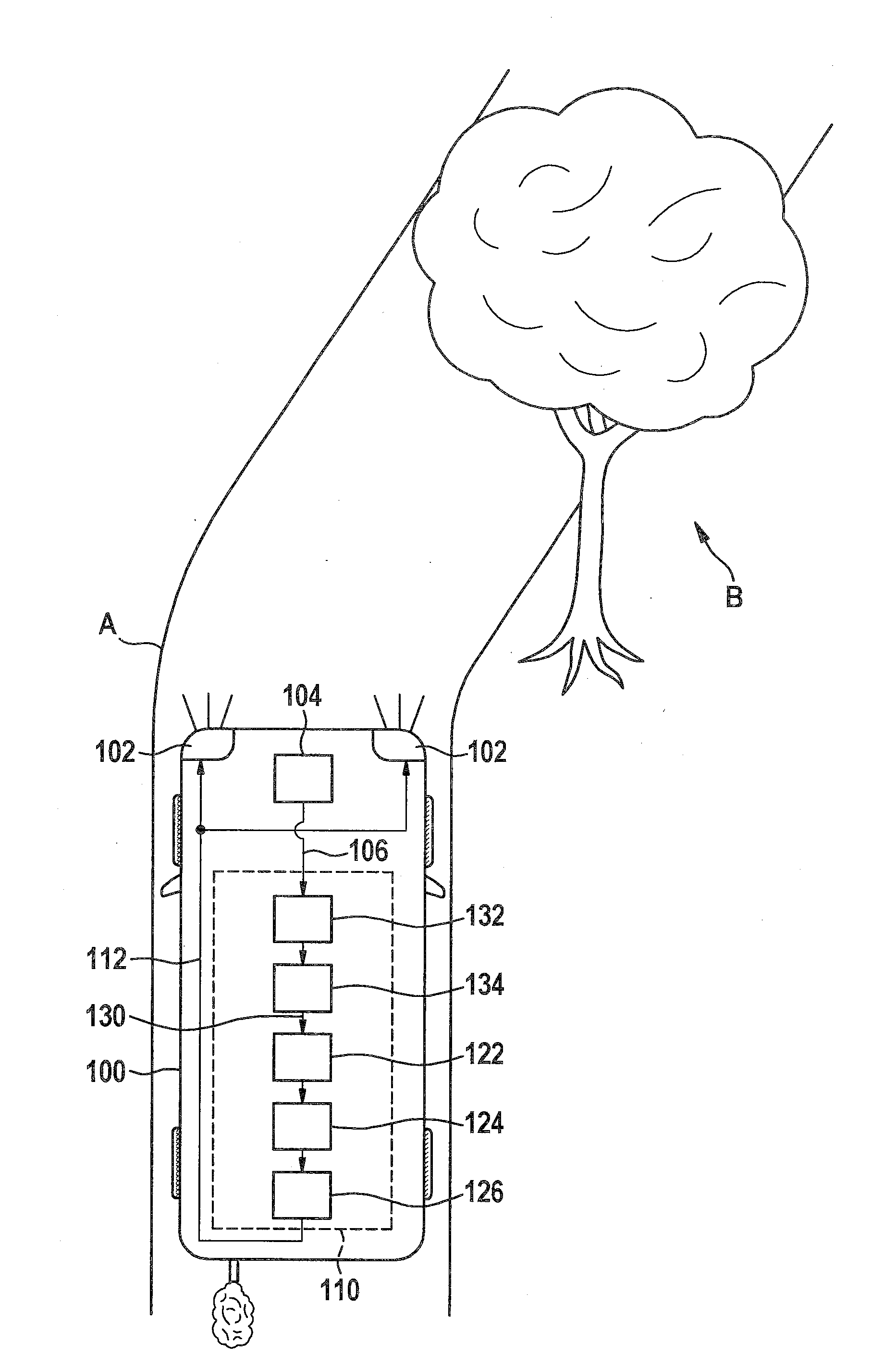
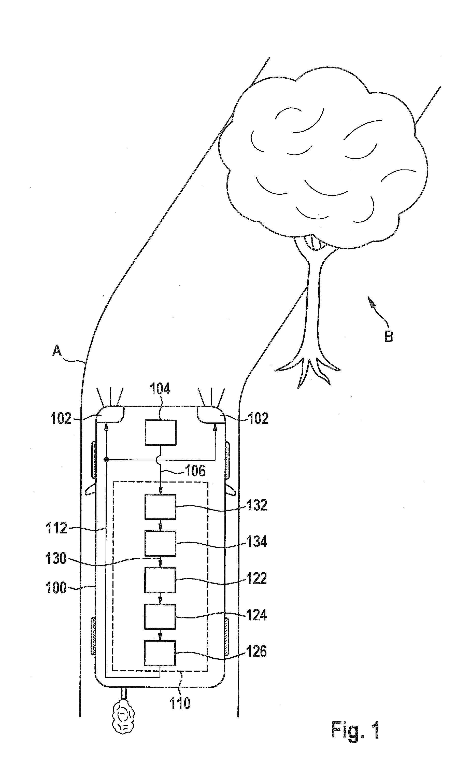
For example, in the case of using a so-called high beam assist, turning the headlights back up or going from a low beam characteristic to a high beam characteristic of a light emission of vehicle headlights may be delayed when concealment objects, for example plants or the like, are situated on the roadside, and therefore an increase in the visual range by turning up the headlights would be too small.

Method used


Image

  • Method and control unit for setting at least one parameter of a driver assistance device of a vehicle
  • Method and control unit for setting at least one parameter of a driver assistance device of a vehicle
  • Method and control unit for setting at least one parameter of a driver assistance device of a vehicle

Examples


Embodiment Construction

[0028]In the following description of advantageous exemplary embodiments of the present invention, identical or similar reference numerals are used for the elements having a similar action which are illustrated in the various figures, and a repeated description of these elements is dispensed with.

[0029]For the purpose of simplification and readability, exemplary embodiments are sometimes described in particular with regard to a classical high beam assist as the driver assistance device, use also being provided for adaptive systems, resulting in a change in system dynamics. In adaptive systems, a short waiting time period corresponds to a rapid system response, as the result of which, for example, a target light distribution or target characteristic is achieved more quickly, and a long waiting time period corresponds to a slower, more sluggish system response, as the result of which a target light distribution or target characteristic is achieved later or more slowly.

[0030]FIG. 1 sho...


PUM


Abstract

A method for setting at least one parameter of a driver assistance device of a vehicle includes reading in concealment data which represent at least one property of at least one concealment object situated adjacent to a roadway in a surroundings of the vehicle. The method also includes ascertaining a concealment-related visual range from the vehicle in an area of the surroundings situated in the forward travel direction ahead of the vehicle, using the concealment data. Finally, the method includes adapting the at least one parameter as a function of the concealment-related visual range.

Description

RELATED APPLICATION INFORMATION[0001]The present application claims priority to and the benefit of German patent application no. 10 2014 225 517.1, which was filed in Germany on Dec. 11, 2014, the disclosure of which is incorporated herein by reference.FIELD OF THE INVENTION[0002]The present invention relates to a method for setting at least one parameter of a driver assistance device of a vehicle, a corresponding control unit, and a corresponding computer program.BACKGROUND INFORMATION[0003]High beam assistance systems may adapt a light distribution to an environmental situation. A customary high beam assist (HBA) may automatically switch over between low-beam light and high-beam light, and adaptive systems may dynamically adapt the light distribution to a traffic situation. Adaptive systems include, for example, assistance systems such as adaptive high beam control (AHC), adaptive cut-off line (aCOL), or adaptive light-dark cutoff, which, similar to headlight leveling control, may...

Claims


Application Information

Patent Timeline
Patent Type & Authority Applications(United States)
IPC IPC(8): B60Q1/08
CPCB60Q1/085B60Q2300/322B60Q2300/05B60Q1/08B60Q1/1423B60Q2300/32B60Q2300/30B60Q2300/052B60Q1/143B60Q2300/45B60Q2300/42
Inventor FOLTIN, JOHANNES
Owner ROBERT BOSCH GMBH
Learn More