

Leakage determining method, substrate processing apparatus and storage medium
Inactive Publication Date: 2016-06-16
TOKYO ELECTRON LTD
View PDF3 Cites 138 Cited by
- Summary
- Abstract
- Description
- Claims
- Application Information
AI Technical Summary
Benefits of technology
[0010]In view of the above, the disclosure provides a leakage determining method for determining whether or not atmospheric air enters a vacuum transfer chamber to which a pressure control gas is supplied, a substrate processing apparatus, and a storage medium in which the method is stored.
[0011]In accordance with an aspect of present invention, there is provided a leakage determining method for determining whether or not atmospheric air enters a vacuum transfer chamber for transferring a substrate under a vacuum atmosphere between at least one preliminary vacuum chamber and at least one processing chamber, the vacuum transfer chamber being connected to the preliminary vacuum chamber of which inner atmosphere is switchable between an atmospheric atmosphere and a vacuum atmosphere and to the processing chamber where the substrate is processed under a vacuum atmosphere
Problems solved by technology
However, there is no description in any of Japanese Patent Application Publication Nos. 2006-261296 and 2013-201292 that a vacuum transfer chamber is provided outside the processing chamber
Method used
View moreImage
Smart ImageViewing Examples


Examples
 PUM
 Abstract
A leakage determining method determines whether or not atmospheric air enters a vacuum transfer chamber for transferring a substrate under a vacuum atmosphere between a preliminary vacuum chamber and a processing chamber. The method includes controlling a pressure in the vacuum transfer chamber to a preset pressure by supplying a pressure control gas into the vacuum transfer chamber; performing supply control, when the substrate is not transferred, by reducing the amount of the pressure control gas supplied into the vacuum transfer chamber or stopping the supply of the pressure control gas; and measuring an oxygen concentration in the vacuum transfer chamber after the supply control of the pressure control gas and determining leakage of atmospheric air into the vacuum transfer chamber by determining whether or not atmospheric air whose amount exceeds a preset allowable level enters the vacuum transfer chamber based on temporal changes of the measured oxygen concentration.
Description
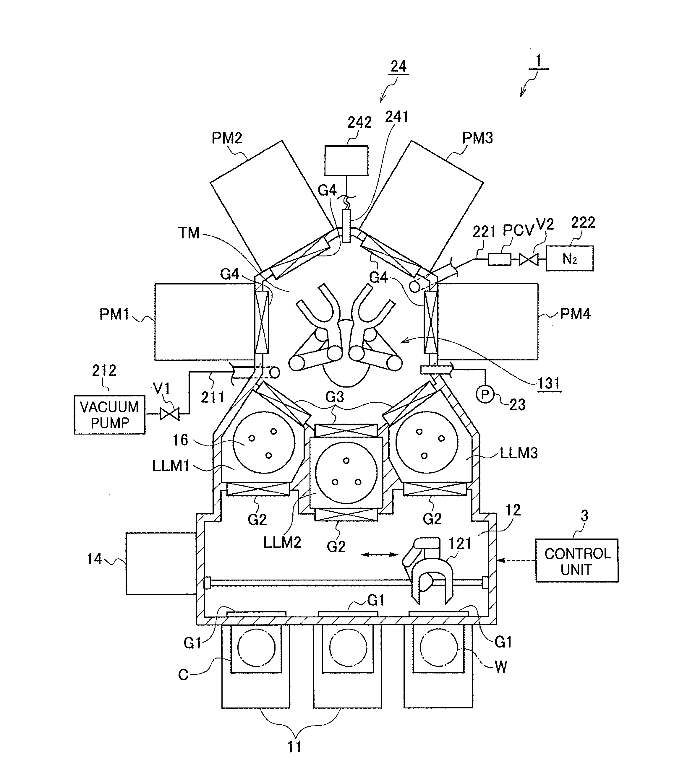
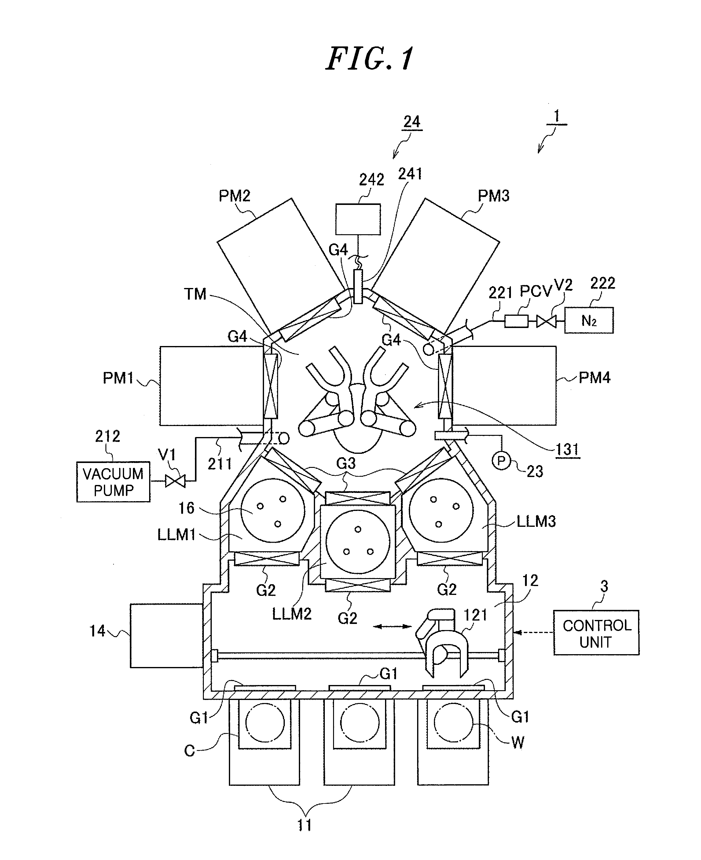
CROSS-REFERENCE TO RELATED APPLICATION[0001]This application claims priority to Japanese Patent Application No. 2014-251085 filed on Dec. 11, 2014, the entire contents of which are incorporated herein by reference.FIELD OF THE INVENTION[0002]The disclosure relates to a technique for determining whether or not atmospheric air enters a vacuum transfer chamber where a substrate is transferred under a vacuum atmosphere.BACKGROUND OF THE INVENTION[0003]In a semiconductor device manufacturing process, there are used various processing modules for processing a wafer in a processing chamber set to a vacuum atmosphere, such as a film forming module for forming a film by reaction of a reactant gas on a surface of a semiconductor wafer (hereinafter, referred to as “wafer”), a plasma processing module for processing the film formed on the surface of the wafer by using a plasma, and the like. Further, there is known a substrate processing apparatus referred to as a multi-chamber type apparatus o...
Claims
Login to View More Application Information
Patent Timeline
 IPC IPC(8): G01M3/02H01L21/67G01N33/00
CPCG01M3/02G01N33/0036H01L21/67098H01L21/67253H01L21/67196G01M3/205G01M3/3209G01M3/226G01M3/3272
InventorISHIBASHI, SEIJISAKAUE, HIROMITSUSASAKI, YOSHIAKI
OwnerTOKYO ELECTRON LTD