Stator for rotary electric machine and method for manufacturing the same

a technology of rotary electric machines and stators, which is applied in the manufacture of stator/rotor bodies, dynamo-electric components, windings, etc., can solve problems such as enlarge coil ends, and achieve the effects of reducing the size of coil ends and improving the joint strength of conductor segments

Inactive Publication Date: 2016-06-16
TOYOTA JIDOSHA KK
View PDF6 Cites 23 Cited by
  • Summary
  • Abstract
  • Description
  • Claims
  • Application Information

AI Technical Summary

Benefits of technology

[0018]According to the stator for the rotary electric machine and the method for manufacturing the same in the present invention, the joint section of the conductor segments is provided in the slot. Therefore, reliability of joint strength of the conductor segments can be improved. Furthermore, compared to a case where the joint section is provided in a coil end, the size of the coil end can be reduced.

Problems solved by technology

This leads to enlarge the coil end.

Method used


Image

  • Stator for rotary electric machine and method for manufacturing the same
  • Stator for rotary electric machine and method for manufacturing the same
  • Stator for rotary electric machine and method for manufacturing the same

Examples


Embodiment Construction

[0034]A description will hereinafter be made on an embodiment according to the present invention with reference to the drawings. In the following description, a stator coil is arranged in a stator core by distributed winding. However, the following description does not limit a winding method of the stator coil. The stator coil may be arranged in the stator core by concentrated winding or wave winding. In the following description, same components in all of the drawings are denoted by the same reference numerals.

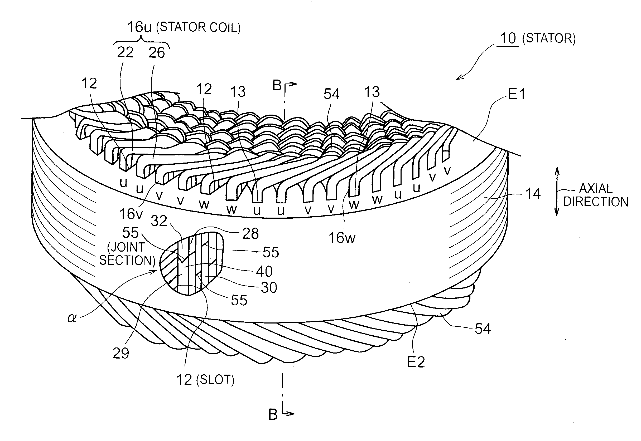
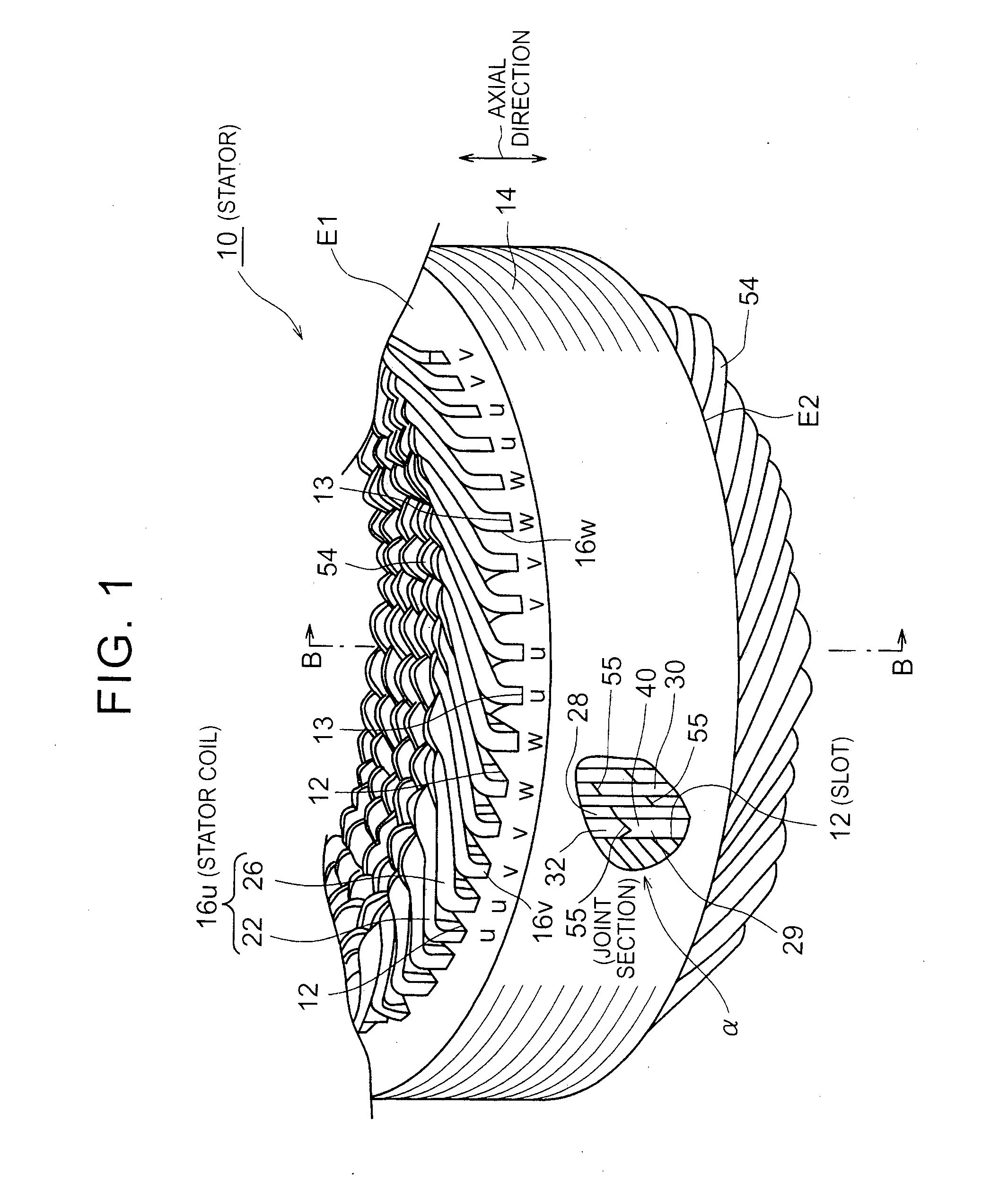
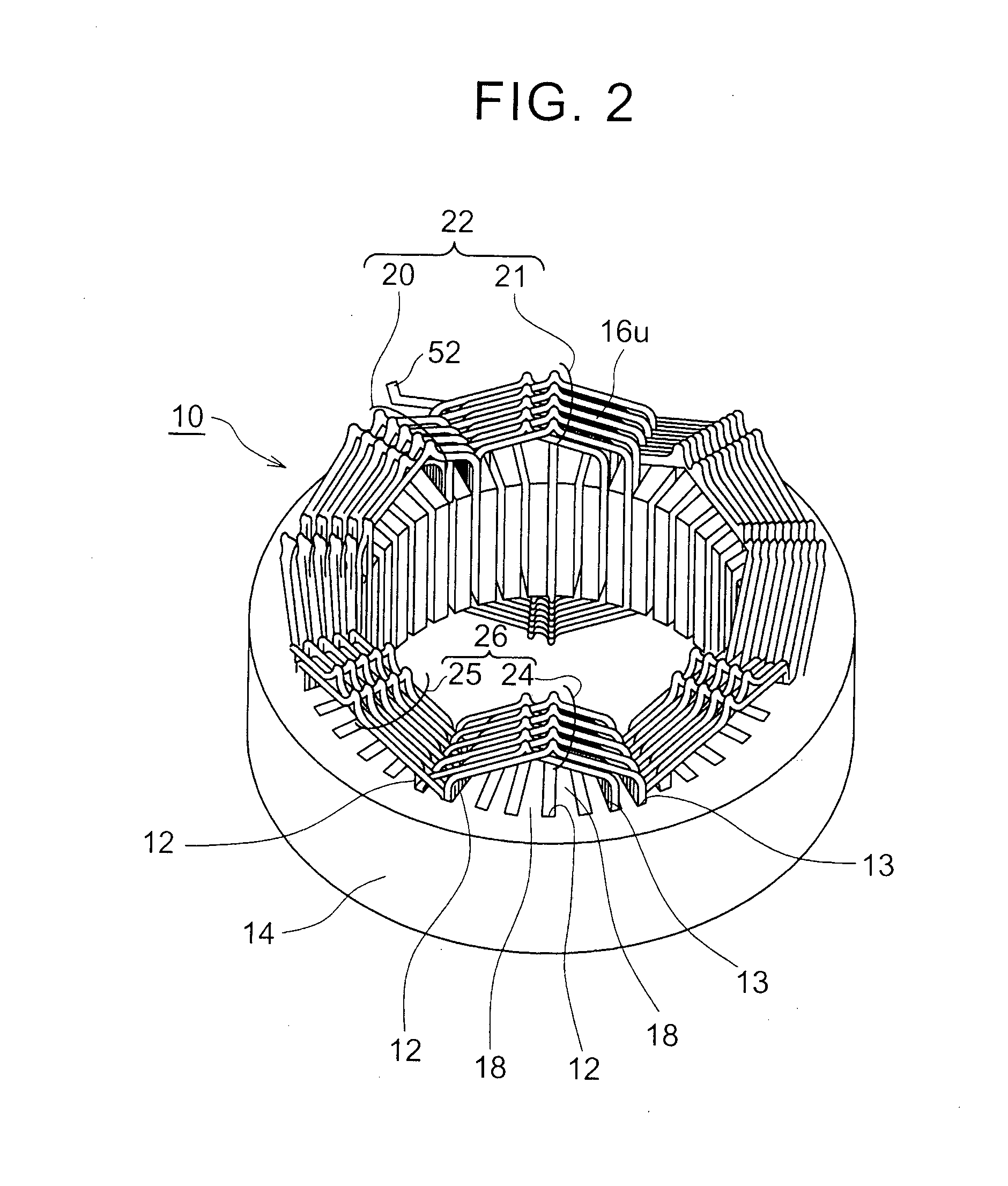
[0035]FIG. 1 is a perspective view for showing arrangement of components in slots 12, 13 in a fractured section a in a stator 10 for a rotary electric machine. FIG. 2 is a view for showing a circumference where a single-phase coupling stator coil 16u is wound in the stator 10 for the rotary electric machine in FIG. 1. The stator 10 for the rotary electric machine will hereinafter be simply referred to as the “stator 10”. The stator 10 is combined with a rotor (not shown) to f...


PUM


Abstract

Stator for rotary electric machine has stator core and stator coil. The stator core has plural slots. The stator coil has a one-side conductor segment, a first other-side conductor segment, and a second other-side conductor segment. In the one-side conductor segment, a first leg and a second leg are inserted in first and second slots from one axial end side of the stator core. In the first other-side conductor segment, a third leg is inserted in the first slot from another axial end side of the stator core. In the second other-side conductor segment, a fourth leg is inserted in the second slot from the other axial end side of the stator core. The stator coil is formed such that the opposing legs are joined in each of the slots and a plurality of the one-side conductor segment and a plurality of the other-side conductor segment are sequentially joined.

Description

BACKGROUND OF THE INVENTION[0001]1. Field of the Invention[0002]The present invention relates to a stator for a rotary electric machine that includes a stator core having plural slots and a stator coil sequentially joining plural conductor segments and wound around the stator core and a method for manufacturing the same, and in particular to joining of plural conductor segments.[0003]2. Description of Related Art[0004]A structure has been known that includes, as a stator for a rotary electric machine, a stator core in which plural slots are formed in a circumferential direction and a stator coil that is wound around the stator core. The stator core is inserted in the plural slots.[0005]Japanese Patent Application Publication No. 2011-239651 (JP 2011-239651 A) discloses that, when the stator coil is formed by joining plural conductor segments, a joint section of the conductor segments is provided at a coil end. The coil ends are provided on the outside of both axial ends of the stato...

Claims


Application Information

Patent Timeline
Patent Type & Authority Applications(United States)
IPC IPC(8): H02K3/28H02K15/02H02K3/12
CPCH02K3/28H02K15/02H02K3/12H02K15/085H02K3/48H02K15/064
Inventor HATTORI, HIROYUKI
Owner TOYOTA JIDOSHA KK
Why Eureka
Try Eureka