
Ball land structure having barrier pattern

Inactive Publication Date: 2010-07-01
SAMSUNG ELECTRONICS CO LTD
View PDF8 Cites 12 Cited by
  • Summary
  • Abstract
  • Description
  • Claims
  • Application Information

AI Technical Summary

Benefits of technology

[0008]Example embodiments provide a ball land structure in which a solder ball joint portion is not voluntary disconnected, thus reinforcing solder ball joint reliability.
[0009]Example embodiments also provide a ball land structure which may enhance stress characteristics that may be degraded in a core portion adjacent to a ball land when the core is partially exposed, thus enhancing solder ball joint reliability.
[0010]Example embodiments also provide a ball land structure having an NSMD (non-soldermask defined) ball land structure suggested to enhance solder ball joint reliability, which may prevent or retard a pattern crack in which an input / output pattern adjacent to a ball land may be disconnected by also enhancing stress characteristics.
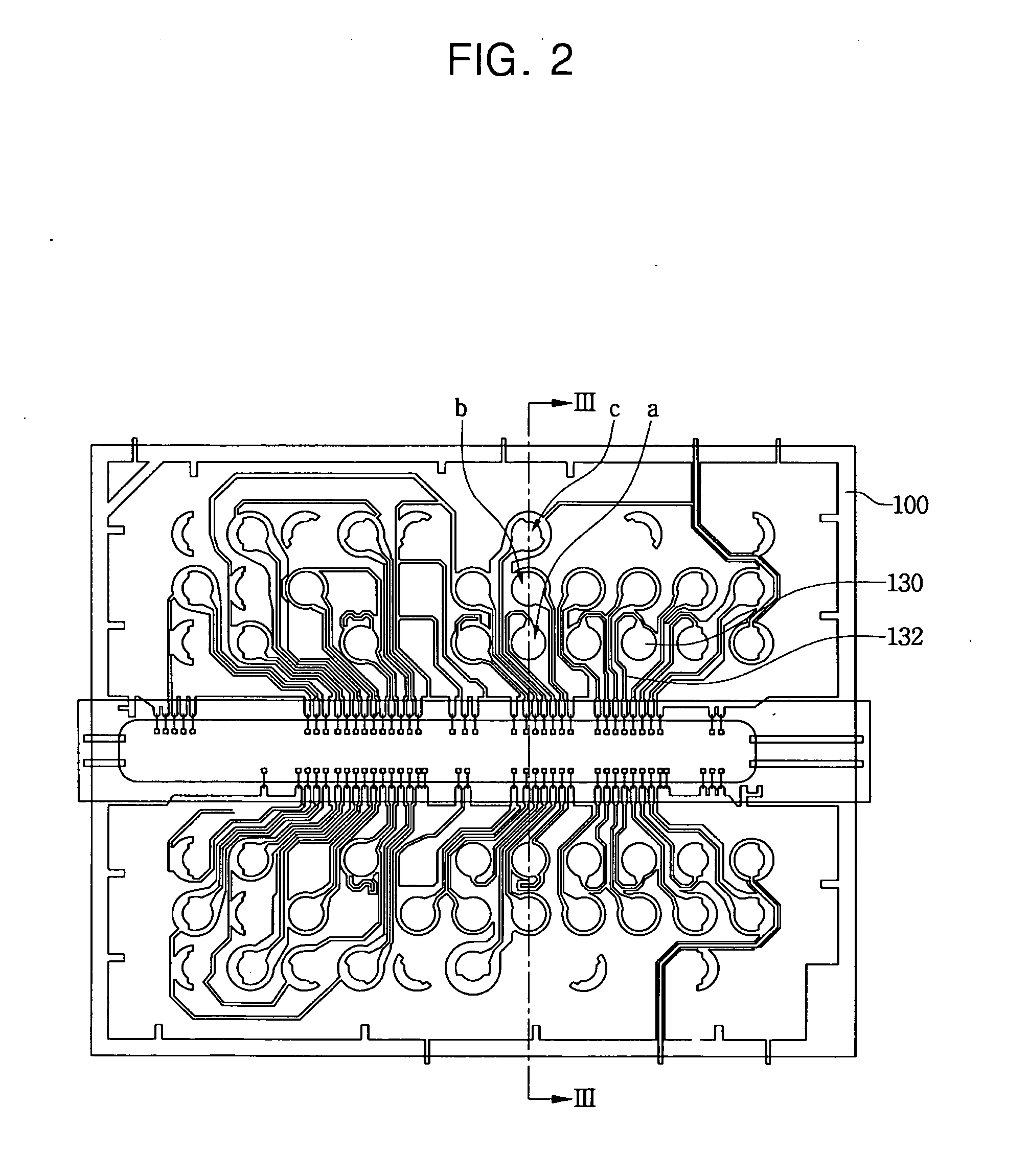
[0017]Example embodiments also provide for a ball land structure including a ball land pattern fused with solder balls, an input / output pattern connected with the ball land pattern, and a barrier configured to surround at least a part of a core whose surface adjacent to the ball land is partially exposed to enhance joint reliability of the solder balls with respect to the ball land, thereby preventing or retarding propagation of a crack that may cause disconnection of the input / output pattern when stress is concentrated at the exposed surface of the core.
[0018]In accordance with example embodiments, the solder ball joint reliability (SJR) may increase as the exposed region of the core becomes larger, the stress may increase as the exposed region of the core becomes larger, and the barrier pattern may be a ring-type pattern preventing or retarding propagation of the crack in the core to a crack in the input / output pattern.

Problems solved by technology

However, in QFP technology, a lead may be easily damaged by impact due to the relatively small pitch.
When the solder ball joint portion is disconnected, electrical disconnection occurs, resulting in fatal defects in the device.
Particularly, when a crack is generated due to damage at a joint portion, an electrical resistance in the joint portion increases, so that electrical characteristics of the package device cannot be ensured.
When the electrical resistance in the solder joint portion increases, DC voltage drop occurs in a signal transmission path, charge delay of an RC circuit may be induced, and noise is generated on a system level.

Method used


Image

  • Ball land structure having barrier pattern
  • Ball land structure having barrier pattern
  • Ball land structure having barrier pattern

Examples


Embodiment Construction

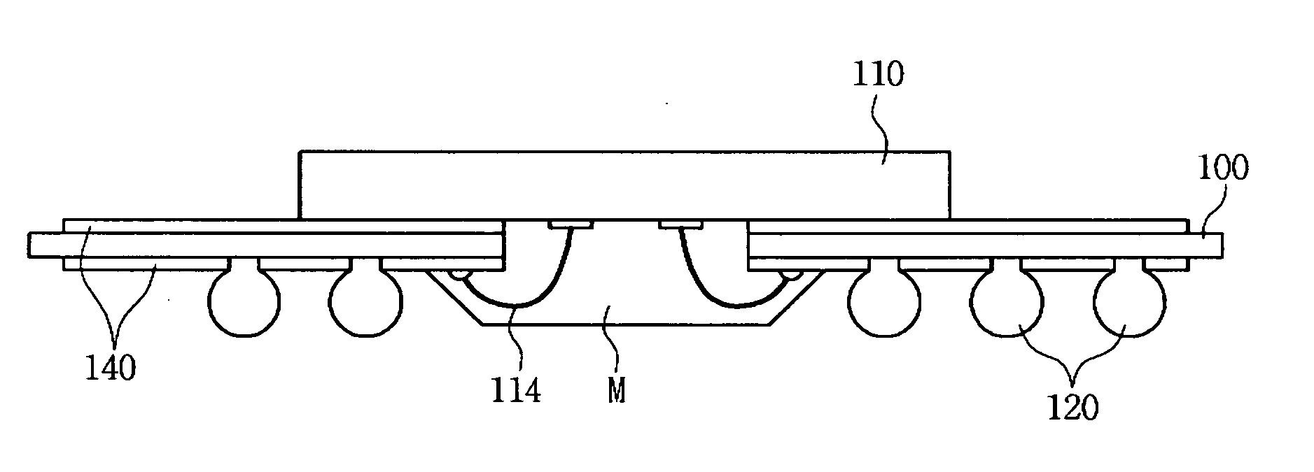
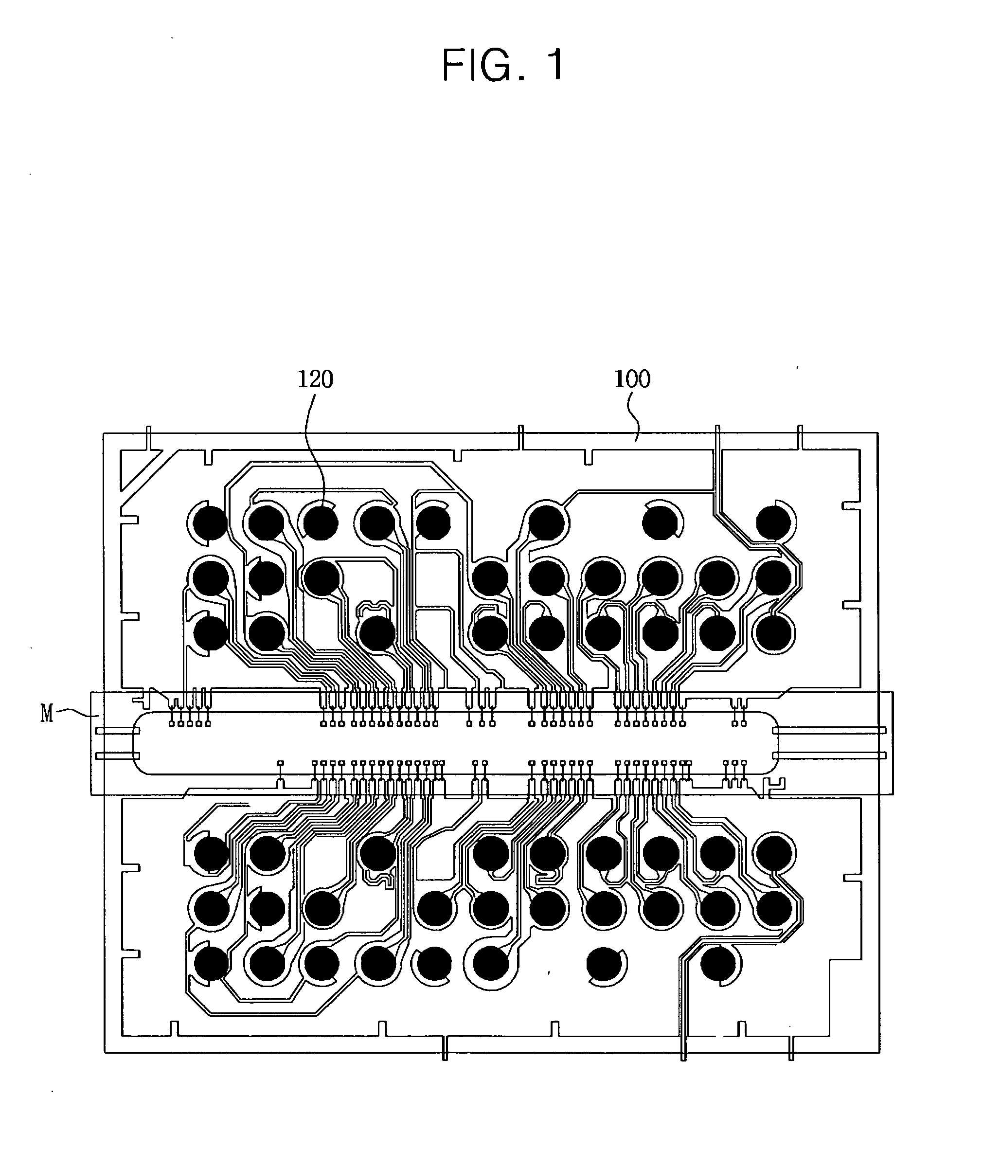
[0033]Example embodiments will now be described more fully with reference to the accompanying drawings in which example embodiments are shown. In the drawings, the thicknesses of layers and regions may be exaggerated for clarity.

[0034]Example embodiments are disclosed herein. However, specific structural and functional details disclosed herein are merely representative for purposes of describing example embodiments. This invention, however, may be embodied in many alternate forms and should not be construed as limited to only example embodiments set forth herein.

[0035]Accordingly, while example embodiments are capable of various modifications and alternative forms, example embodiments thereof are shown by way of example in the drawings and will herein be described in detail. It should be understood, however, that there is no intent to limit example embodiments to the particular forms disclosed, but on the contrary, example embodiments are to cover all modifications, equivalents, and...


PUM


Abstract

Disclosed is a ball land structure suitable for use with a semiconductor package. The ball land structure includes a ball land and a barrier on a core. The barrier may be configured to connect to the ball land so as to form a barrier hole between an edge of the ball land and an edge of the barrier thus exposing a portion of the core. A solder mask may be deposited on the ball land and a portion of the core exposed by the barrier hole so as to partially expose the core.

Description

PRIORITY STATEMENT[0001]This application claims priority under 35 U.S.C. §119 to Korean Patent Application No. 10-2008-0137857, filed on Dec. 31, 2008, in the Korean Intellectual Property Office (KIPO), the entire contents of which are herein incorporated by reference.BACKGROUND[0002]1. Field[0003]Example embodiments relate to a ball land structure having a barrier surrounding an exposed region of a core which may prevent or retard propagation of a core crack to a neighboring pattern crack.[0004]2. Description of Related Art[0005]In response to a trend aiming at compact and lightweight integrated circuit devices having relatively high reliability, there are increasing demands for smaller package devices having more input / output pins. A quad flat package (QFP) and a ball grid array (BGA) package are capable of providing many input / output pins, which correspond to this recent trend.[0006]In QFP technology, the leads may be spaced to have a relatively small pitch. Thus, BGA package tec...

Claims


Application Information

Patent Timeline
IPC IPC(8): H01L23/498H01R12/04
CPCH01L23/13H01L23/49811H01L24/48H01L24/97H01L2224/48091H01L2224/4824H01L2224/73215H01L2224/97H01L2924/01015H01L2924/01029H01L2924/01047H01L2924/01082H01L2924/14H01L2924/15311H05K1/111H05K3/3452H05K2201/0969H05K2201/09781H05K2201/0989H05K2201/099H01L2924/00014H01L2224/85H01L2924/01005H01L2924/01006H01L2924/01023H01L2924/01033H01L2924/01043H01L2924/181H01L2924/00Y02P70/611H01L2224/45099H01L2224/45015H01L2924/207Y02P70/50
Inventor LEE, WANG-JAEJUNG, YONG-JINKIM, JUNG-HYEON
Owner SAMSUNG ELECTRONICS CO LTD
Learn More