duplexer

a technology of duplexers and spherical plates, applied in the direction of impedence networks, electrical equipment, piezoelectric/electrostrictive/magnetostrictive devices, etc., can solve the problems of insufficient increase of attenuation outside the pass band of the reception filter, deterioration of isolation characteristics in the pass band of the transmission filter, etc., to improve isolation characteristics, increase attenuation, increase the effect of attenuation

a technology of duplexers and spherical plates, applied in the direction of impedence networks, electrical equipment, piezoelectric/electrostrictive/magnetostrictive devices, etc., can solve the problems of insufficient increase of attenuation outside the pass band of the reception filter, deterioration of isolation characteristics in the pass band of the transmission filter, etc., to improve isolation characteristics, increase attenuation, increase the effect of attenuation

US20160173061A1Active Publication Date: 2016-06-16MURATA MFG CO LTD

Image

  • duplexer
  • duplexer
  • duplexer

Examples


Embodiment Construction

[0030]Preferred embodiments of the present invention will herein be described with reference to the attached drawings to illustrate the present invention.

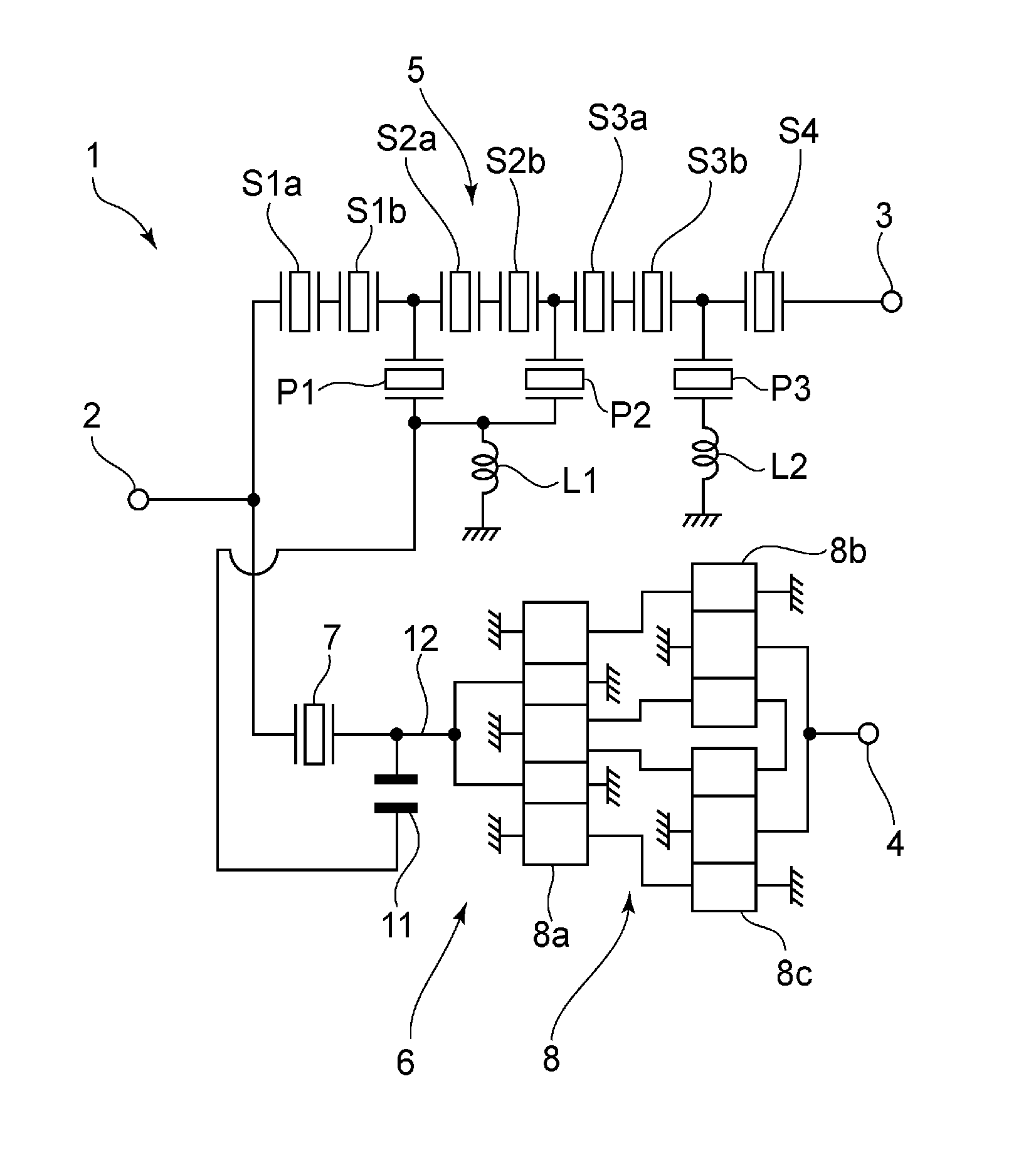
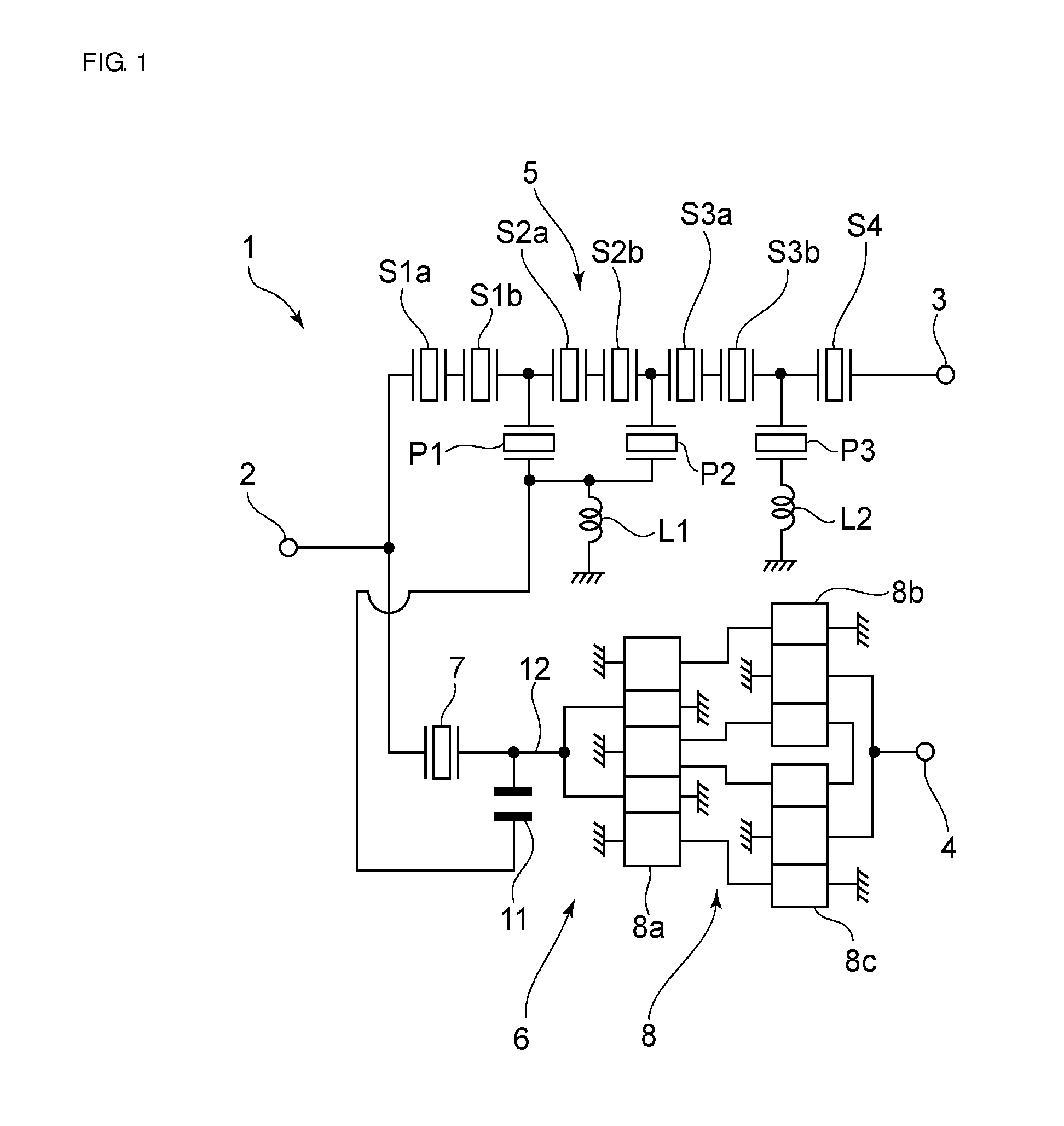
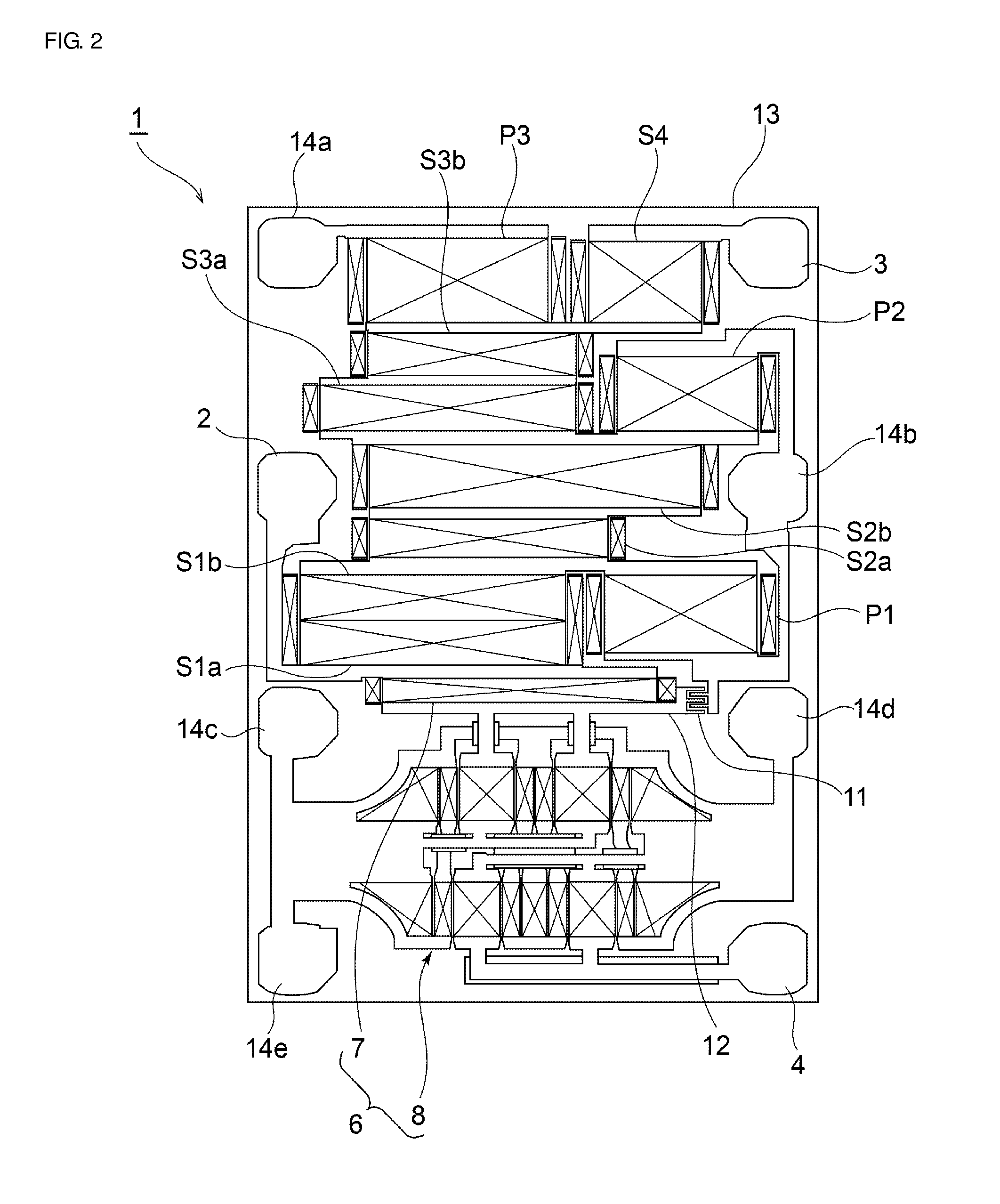
[0031]FIG. 1 is a circuit diagram of a duplexer according to a first preferred embodiment of the present invention. FIG. 2 is a schematic plan view of the duplexer of the present preferred embodiment.

[0032]A duplexer 1 includes an antenna terminal 2, a transmission terminal 3, and a reception terminal 4. A transmission filter 5 is connected between the antenna terminal and the transmission terminal 3. The transmission filter 5 includes a ladder filter. Specifically, the transmission filter includes multiple serial arm resonators S1a, S1b to S4. Specifically, the multiple serial arm resonators S1a, S1b to S4 are connected in series to each other in a serial arm connecting the antenna terminal 2 to the transmission terminal 3. First to third parallel arms are connected between the serial arm and ground potential.

[0033]The first paral...


PUM


Abstract

A duplexer includes a transmission filter with a ladder circuit configuration and a reception filter. The reception filter includes a series trap element connected to an antenna terminal and a longitudinally coupled resonator-type surface acoustic wave filter. In the transmission filter, a coupling capacitance is connected between an end portion at parallel arm resonators side of an inductance and a line connecting the series trap element to the longitudinally coupled resonator-type surface acoustic wave filter in the reception filter.

Description

BACKGROUND OF THE INVENTION[0001]1. Field of the Invention[0002]The present invention relates to duplexers used for, for example, mobile communication terminals. More particularly, the present invention relates to a duplexer including a transmission filter with a ladder circuit configuration that includes multiple elastic wave resonators.[0003]2. Description of the Related Art[0004]Duplexers using surface acoustic wave filters have hitherto been widely used in, for example, mobile communication terminals. For example, Japanese Unexamined Patent Application Publication No. 2004-96250 discloses a surface acoustic wave filter having a ladder circuit configuration as a transmission filter of a duplexer. In Japanese Unexamined Patent Application Publication No. 2004-96250, an antenna terminal, a transmission terminal, and a ground terminal are provided on a piezoelectric substrate. The transmission filter having the ladder circuit configuration is provided between the antenna terminal, t...

Claims


Application Information

Patent Timeline
16 Jun 2016
Publication
US20160173061A1
IPC
H03H9/72
CPC
H03H9/725; H03H9/0009; H03H9/6433; H03H9/6479; H03H9/6483
Inventors
TAKAMINE, YUICHI