

Directional coupler
A technology of directional coupler and coupling port, which is applied in the direction of waveguide devices, electrical components, connecting devices, etc., to achieve the effect of suppressing large-scale, good isolation characteristics and orientation
- Summary
- Abstract
- Description
- Claims
- Application Information
AI Technical Summary
Problems solved by technology
Method used
Image

Examples
no. 1 Embodiment approach 》
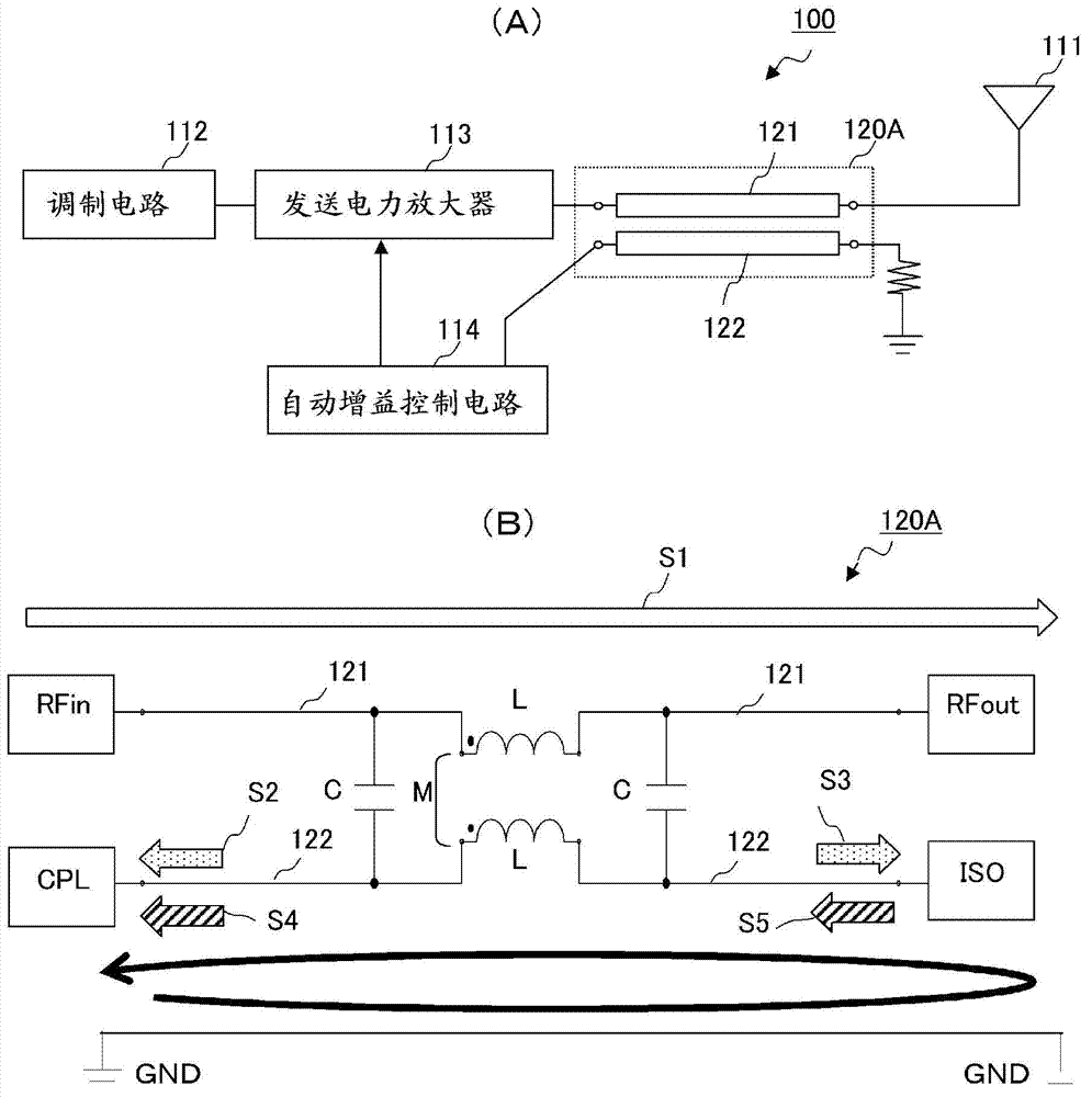
[0039] Figure 5 (A) is an equivalent circuit diagram of the transmission line type directional coupler 20A according to the first embodiment of the present invention.
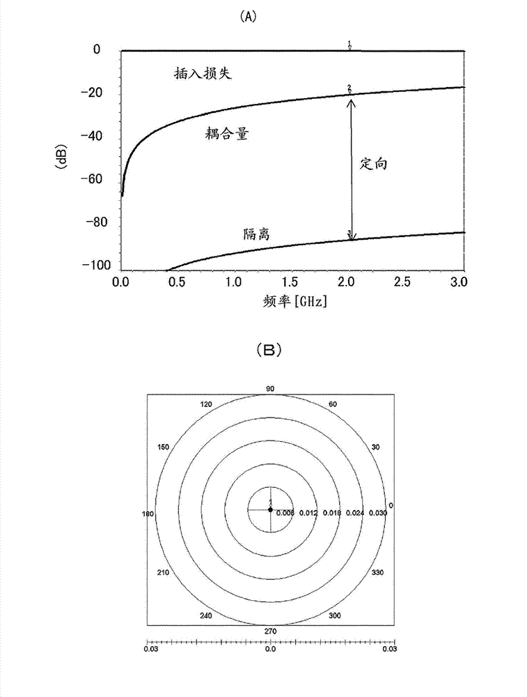
[0040] The directional coupler 20A includes a main line 21 and a sub line 22 . The main line 21 and the sub-line 22 each have an inductance L, and are capacitively coupled to each other through a distributed capacitance C between the lines, and magnetically coupled through a mutual inductance M. The main line 21 has a signal input port RFin and a signal output port RFout. The secondary line 22 has a coupled port CPL and an isolated port ISO. In the sub-line 22, the signal caused by electric field coupling and the signal caused by magnetic field coupling at the coupled port CPL are in phase and constructive, and the signal caused by electric field coupling and the signal caused by magnetic field coupling at the isolation port ISO are in antiphase and cancel.
[0041] If it is an ideal directional coupler, b...
no. 2 Embodiment approach 》
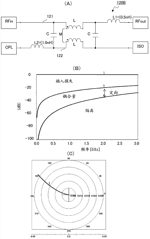
[0049] Next, the directional coupler 20B of the second embodiment will be described. Figure 7 (A) is an equivalent circuit diagram of the directional coupler 20B, and the directional coupler 20B is configured by inserting the series capacitor Cx' (= C2 = 6 pF) only in the coupling port CPL.
[0050] In this composition, if Figure 7 As shown in the frequency characteristics and isolation characteristics of (B) and 7(C), since the resonant frequency of the series capacitor Cx' deviates from the desired frequency (about 2.0 GHz), the improvement effects of isolation and orientation are limited, and can only be expected Some degree of isolation and orientation improvement. However, at least the series capacitor C1 conventionally provided at the signal output port RFout is omitted, so that the device size can be suppressed by the amount of the series capacitor C1, and the insertion loss caused by inserting the series capacitor C1 into the main line 21 can also be suppressed. de...
no. 3 Embodiment approach 》
[0052] Next, 20 C of directional couplers of 3rd Embodiment are demonstrated. Figure 8 (A) is an equivalent circuit diagram of the directional coupler 20C, and the directional coupler 20C is configured by inserting a series capacitor Cx (=4.2 pF) only in the signal output port RFout.
[0053] In this composition, if Figure 8 As shown in the frequency characteristics and isolation characteristics of (B) and 8(C), since the resonance frequency of the series capacitor Cx becomes the desired frequency (about 2.0 GHz), some degree of isolation and directional improvement can be expected. In addition, since at least the series capacitor C2 conventionally provided at the coupling port CPL is omitted, the device size can be suppressed by the amount of the series capacitor C2. However, some deterioration of insertion loss occurs due to the insertion of the series capacitor Cxhi into the main line 21 . Therefore, it is considered that it is preferable to connect a series capacitance...
PUM
 Abstract
Description
Claims
Application Information