

Exhaust apparatus of vehicles
An exhaust device and vehicle technology, which is applied in the directions of exhaust device, muffler device, and air quality improvement, can solve the problem of increasing the size of the muffler, and achieve the effect of suppressing the increase in size.
- Summary
- Abstract
- Description
- Claims
- Application Information
AI Technical Summary
Problems solved by technology
Method used
Image

Examples
Embodiment 1
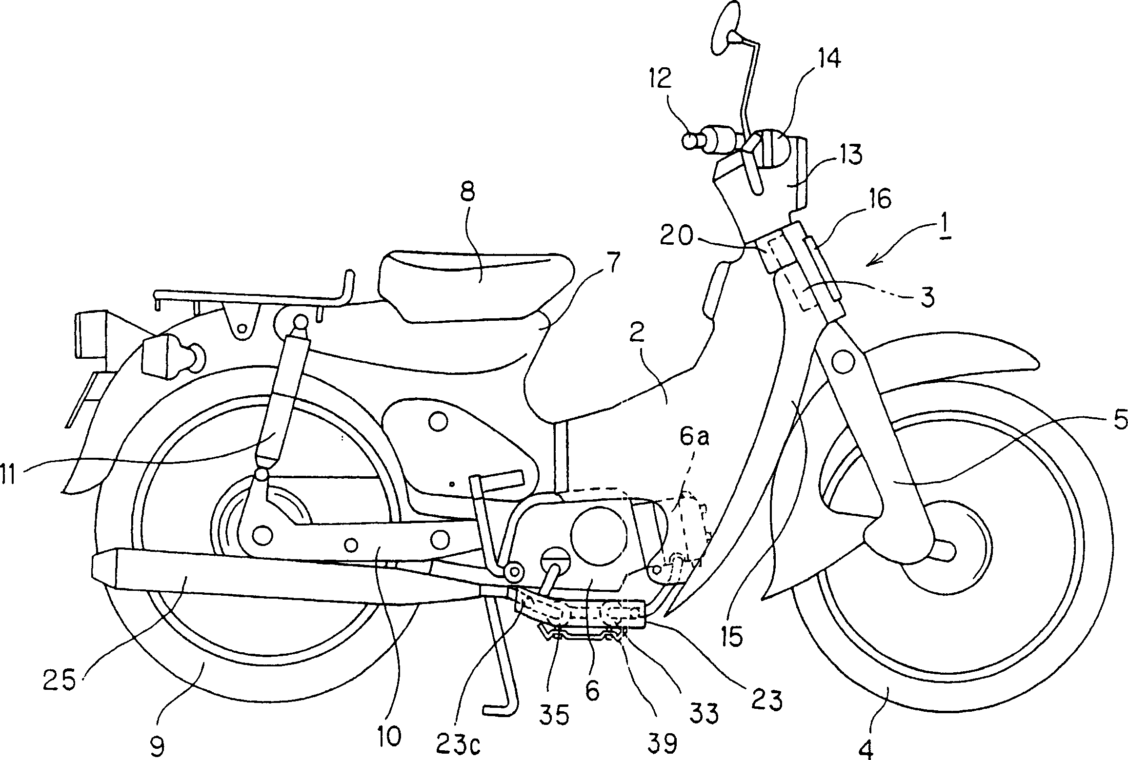
[0036] exist figure 1 Among them, 1 is a motorcycle (vehicle), and this motorcycle 1 is constituted by covering the front part of a stamped frame 7 with a cover 2 . A front fork 5 supporting a front wheel 4 is supported on the head pipe 3 at the front of the stamped frame.
[0037] In addition, an engine 6 is installed in the middle lower part of the shield 2, and a fuel tank (not shown) is provided inside the rear of the shield 2. The above-mentioned stamped vehicle frame 7 is continuous in appearance, and a seat 8 is extended on it. . A rear fork 10 for supporting the rear wheel 9 is freely swingably supported at the bottom of the stamped vehicle frame 7, and a rear buffer device 11 is provided between the rear fork 10 and the rear portion of the vehicle frame. On the top of the steering shaft extending toward the head pipe 3, a handlebar 12 is attached. At the center of the handlebar 12, a headlight device 13 is attached.
[0038] On the left and right sides of the front...
Embodiment 2
[0065] Figure 7 and Figure 8 Example 2 is shown.
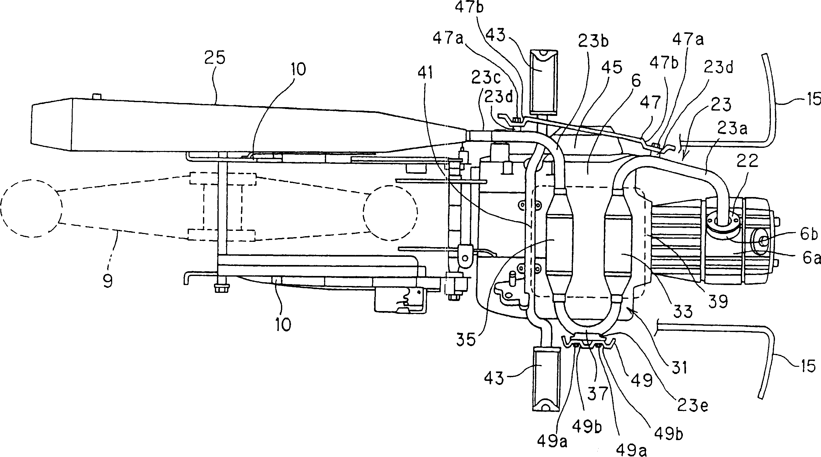
[0066] In this example, as Figure 7 As shown, the curved portion 231 constitutes a part of the exhaust pipe 23, and is located directly below the engine 6, and in order to be accommodated within the width of the engine 6, there is also an upstream side catalytic converter whose axis extends in the front-rear direction of the vehicle. The exhaust cleaner 233, the downstream catalytic converter 235 with the same axis extending in the vehicle front-rear direction, and the curved pipe 237 connecting the exhaust cleaners 233, 235 in series are U-shaped in plan view. In this case, as Figure 8 As shown, each catalytic exhaust gas purifier 233, 235 can be substantially horizontal to its axis, and is arranged in a transverse direction directly under the engine 6, and the upstream side catalytic exhaust gas purifier 233 is located at a higher position than the downstream side catalytic exhaust gas purifier 233. 235 is still slig...
Embodiment 3
[0073] In addition, this invention is not limited to the said structure, The following deformation|transformation can be implemented.
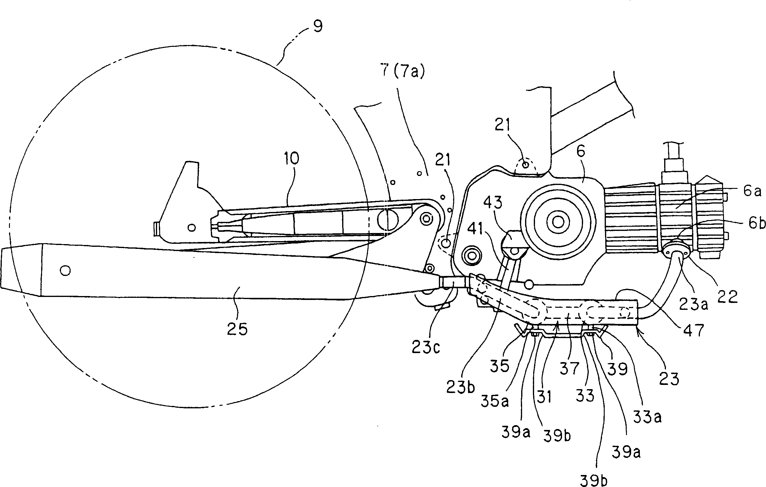
[0074] Figure 9 A diagram showing an exhaust device of a vehicle according to Example 3.
[0075] In Embodiment 3, right below the engine 6, the curved portion 331 is provided with: an upstream side catalytic exhaust gas purifier 333, a downstream side catalytic exhaust gas purifier 335, and each exhaust gas purifier is connected in series and connected from the The U-shaped curved pipe 337 is viewed from above. In this configuration, the upstream catalytic converter 333 and the downstream catalytic converter 335 are integrated to form the composite catalytic converter 36 . The composite catalytic exhaust gas converter 36 is externally composed of an exhaust gas purification part 36c and connection parts 36j provided at both ends thereof. The exhaust purification part 36c is a part functioning as a catalyst, and the connecting part 36j is ...
PUM
 Abstract
Description
Claims
Application Information