
Connecting wire used in stator of electric motor, stator having the connecting wire and bending method of the connecting wire

A technology for connecting wires and motors, applied in the field of connecting wires, can solve problems such as insufficient space for tools, and achieve the effect of suppressing enlargement

Active Publication Date: 2010-06-16
TOYOTA JIDOSHA KK
View PDF1 Cites 9 Cited by
  • Summary
  • Abstract
  • Description
  • Claims
  • Application Information

AI Technical Summary

Problems solved by technology

However, when the distance between the coil main body and the bending position of the coil end is short, it may not be possible to secure enough space for the tool, and the coil end cannot be bent to a desired angle depending on the coil material, diameter, cross-sectional shape, etc.
However, Japanese Patent Application Laid-Open No. 2001-103700 does not disclose a technique for solving the above-mentioned problems

Method used


Image

  • Connecting wire used in stator of electric motor, stator having the connecting wire and bending method of the connecting wire
  • Connecting wire used in stator of electric motor, stator having the connecting wire and bending method of the connecting wire
  • Connecting wire used in stator of electric motor, stator having the connecting wire and bending method of the connecting wire

Examples


Embodiment Construction

[0020] Hereinafter, embodiments of the present invention will be described with reference to the drawings. In the following description, the same reference numerals are assigned to the same components. Their names and functions are also the same. Therefore, their detailed descriptions are not repeated.

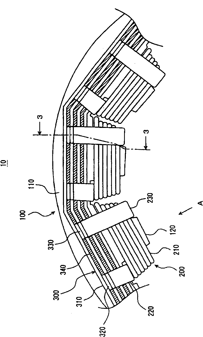
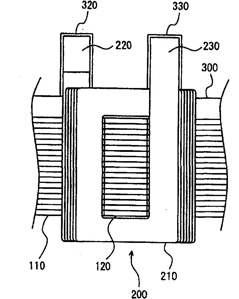
[0021] refer to figure 1 , figure 2 The stator 10 of the motor of this embodiment will be described. figure 1 is a partial plan view of the stator 10 viewed from above. figure 2 From figure 1 The direction A shown is a partial plan view of the stator 10 . The stator 10 includes a stator core 100 , coils 200 , and bus bars 300 .

[0022] The stator core 100 is formed by laminating a plurality of magnetic steel sheets. The stator core 100 includes a stator main body 110 and teeth 120 . The stator main body portion 110 is formed in an annular shape (hollow cylindrical shape) having a constant width over the entire circumference. A plurality of teeth 120 are provided a...


PUM


Abstract

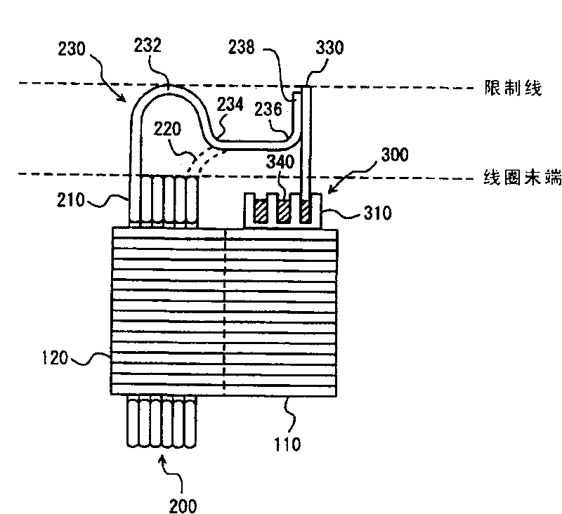
A connecting wire (230) is bent toward a coil main body (210) at a first bending section (232) near a limit line of a length along an axis of a stator core. Furthermore, the connecting wire (230) is bent toward a direction away from the coil main body (210) at a second bending section (234) which is located closer to the coil main body (210) than the first bending section (232). The connecting wire (230) is further bent at a third bending section (236) in a direction away from the coil main body (210) so that a connecting portion (238) comes into contact with, and extends along an end surface of a terminal member (330) substantially in parallel thereto.

Description

technical field [0001] The present invention relates to a connecting wire for a motor stator, and more particularly to a connecting wire for connecting a coil wound on a stator core and a terminal member provided on the outer peripheral side of the core than the coil. Background technique [0002] An electric motor used as a driving source of an electric vehicle generally has an annular stator core provided with a plurality of teeth protruding in the inner circumferential direction at constant intervals in the circumferential direction. A coil is wound around each tooth of the stator core. In order to facilitate assembly, such a stator is manufactured by winding coils in advance according to the shape of each tooth and unitizing them, and fitting each unitized coil to each tooth. In this case, it is necessary to electrically connect the planned coils after each of the unitized coils is fitted to each tooth, and there is a problem that the connection work is difficult. A te...

Claims


Application Information

Patent Timeline
Patent Type & Authority Applications(China)
IPC IPC(8): H02K3/18H02K3/52H02K15/04
CPCH02K15/0075H02K3/522H02K3/18H02K15/0068Y10T29/49009
Inventor 浦野广晓立松和高竹纲靖治西隈靖小松裕
Owner TOYOTA JIDOSHA KK
Learn More