Automatic urine collecting apparatus

An automatic recovery and free technology, applied in medical science, drainage devices, medical transportation, etc., can solve the problems of increased noise and enlarged urine automatic recovery device, and achieve the goal of suppressing large-scale and improving absorption capacity Effect

Inactive Publication Date: 2006-04-26
HITACHI LTD
View PDF1 Cites 9 Cited by
  • Summary
  • Abstract
  • Description
  • Claims
  • Application Information

AI Technical Summary

Problems solved by technology

[0004] However, in the above-mentioned automatic urine recovery device, since the diaphragm pump is generally used as the suction pump, if the suction capacity is to be increased, the pump body itself will be enlarged, so that the entire automatic urine recovery device must be enlarged.
In addition, there is also a problem that the noise generated by the automatic urine recovery device (pump body) increases due to the increase in size of the pump body itself.

Method used


Image

  • Automatic urine collecting apparatus
  • Automatic urine collecting apparatus
  • Automatic urine collecting apparatus

Examples


no. 1 approach

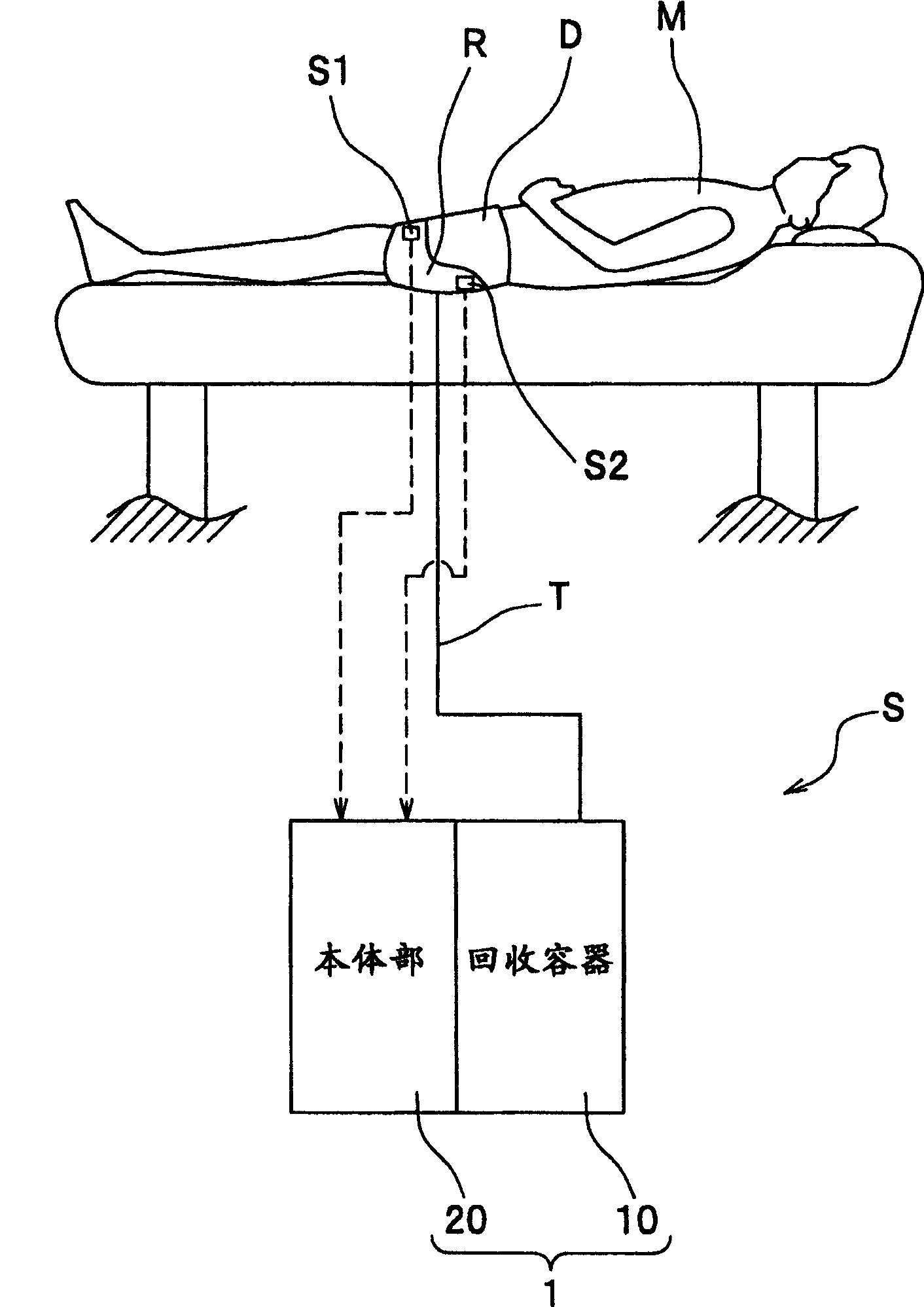
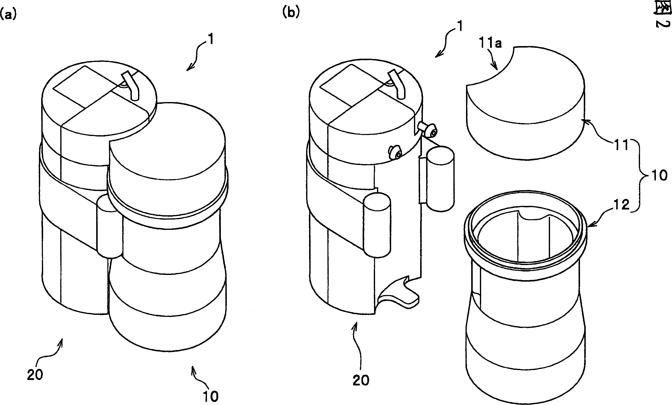
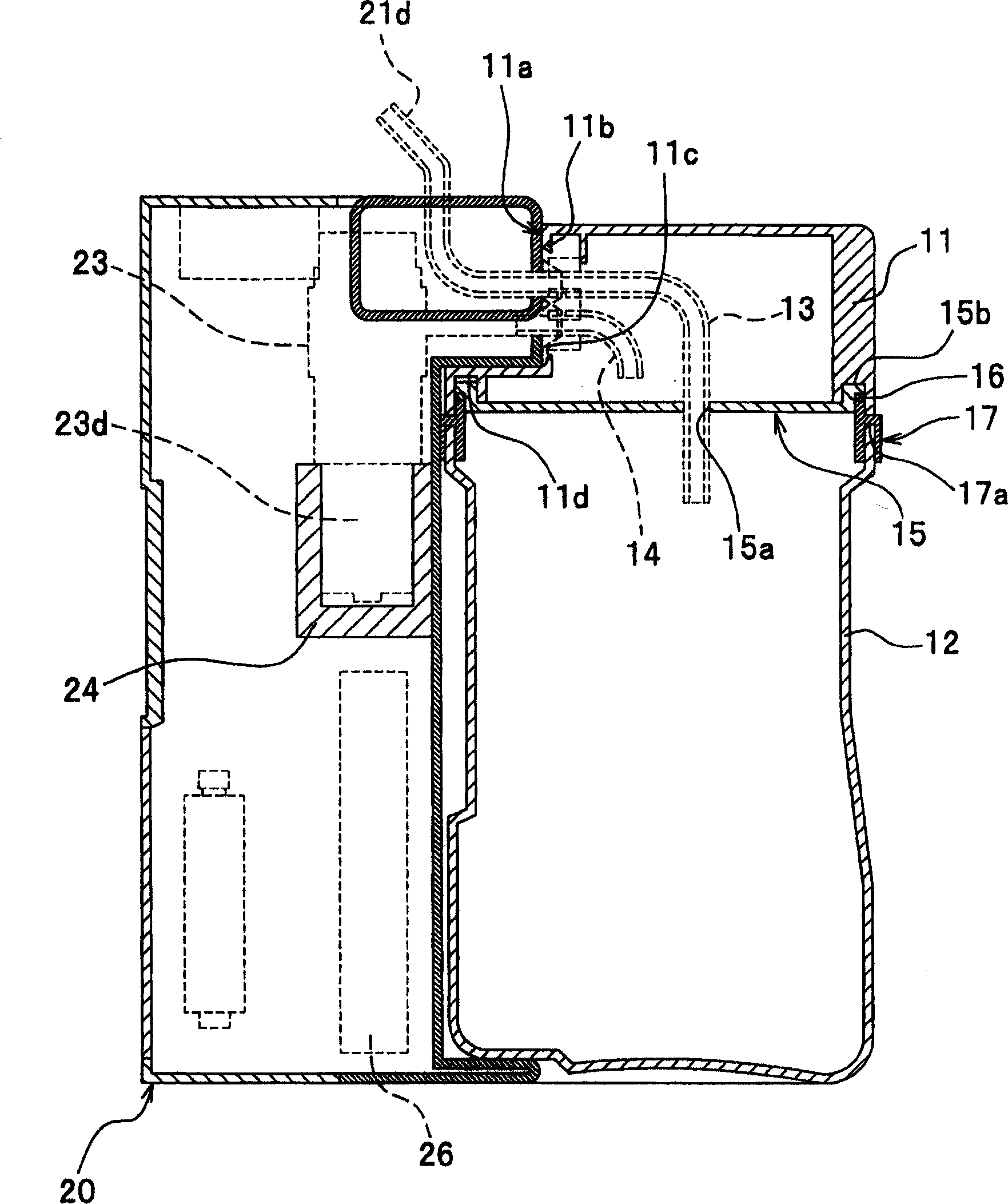
[0022] Hereinafter, a first embodiment of the automatic urine collection device of the present invention will be described in detail with reference to appropriate drawings. In the attached drawings, figure 1 2 is a perspective view (a) showing the automatic urine recovery device of the first embodiment and an exploded perspective view of a state where the main body and the recovery container are disassembled ( b). image 3 It is a longitudinal sectional view showing the internal structure of the automatic urine collection device of FIG. 2 , Figure 4 It is an exploded perspective view showing components of the automatic urine collection device of FIG. 2 . Figure 5 yes means Figure 4 A top view of the display section.

[0023] like figure 1 As shown, the automatic urine recovery system S is mainly composed of a urine receiver R installed on a diaper D for temporarily receiving urine excreted by a patient M, and a urine receiver R that automatically recovers the urine rec...

no. 2 approach

[0054] Next, a second embodiment of the automatic urine collection device of the present invention will be described. Since this embodiment is a modification of the automatic urine collection device 1 of the first embodiment, the same reference numerals are used for the same components as those of the first embodiment, and description thereof will be omitted. In the drawings referred to, FIG. 7 is an exploded perspective view (a) showing a state in which the automatic urine collection device of the second embodiment is disassembled into a main body and a tank part, and a perspective view (a) of a state where the handle of the automatic urine collection device is pulled out ( b) and a perspective view (c) of the state where the handle is pushed in. Fig. 8 is an exploded perspective view showing components of the automatic urine collection device of Fig. 7 .

[0055] As shown in FIGS. 7( a ) to ( c ), the automatic urine collection device 2 has a main body 40 that functions as ...

no. 3 approach

[0064] A third embodiment of the automatic urine collection device of the present invention will be described below. Since this embodiment is a modification of the automatic urine collection device 1 of the first embodiment, the same reference numerals are used for the same components as those of the first embodiment, and description thereof will be omitted. In the attached drawings, Figure 9 It is a perspective view showing the urine automatic recovery device of the third embodiment, and FIG. 10 shows Figure 9 An exploded perspective view of the components of the automatic urine recovery device. in addition, Figure 11 yes means Figure 9 Cross-sectional view of the internal structure of the automatic urine recovery device.

[0065] like Figure 9 As shown, the automatic urine collection device 3 has a main body 60 , a tank 70 , a common lid 80 as a cover for the main body 60 and the tank 70 , and a lifting device 90 for lifting the tank 70 up and down.

[0066] As show...


PUM


Abstract

It is an object of the present invention to provide an automatic urine recovery device capable of increasing the suction capacity of a suction pump while suppressing an increase in the overall size of the device or loud noise generated by the device. The automatic urine recovery device (1) has a recovery container (10) for storing urine delivered from a urine receiver through a hose, and a main body (20) that is freely detachable to the recovery container (10). And, in the main body (20), as a suction pump for sucking the urine received by the urine receiver (R) and transporting it to the recovery container (10), a suction pump with small size, large suction force and quiet noise is provided. The characteristics of the rotary pump (23).

Description

technical field [0001] The present invention relates to an automatic urine recovery device for automatically recovering urine excreted by bedridden patients or elderly people. Background technique [0002] In recent years, an automatic urine recovery system for automatically recovering urine excreted by bedridden patients or elderly people has appeared. The automatic urine collection system is generally mainly composed of a urine receiver attached to the vagina of a patient through a diaper or the like, a hose connected to the receiver at one end, and an automatic urine collection device connected to the other end of the hose. And, as we know, the existing automatic urine recovery device has a recovery container for storing urine discharged from the receiver through a hose, and a suction pump for sucking the urine stored in the above-mentioned urine receiver and transporting it to the recovery container (for example, referring to the patent Literature 1). [0003] [Patent ...

Claims


Application Information

Patent Timeline
Patent Type & Authority Applications(China)
IPC IPC(8): A61F5/44A61G9/00
CPCA61F5/451
Inventor 小泉博司宫川良辅石冢义和田中哲也佐山重治
Owner HITACHI LTD
Why Eureka
Try Eureka