Headlight module for vehicle, headlight unit for vehicle, and headlight device for vehicle

A technology for headlights and vehicles, which is applied to lighting devices, fixed lighting devices, headlights, etc., can solve the problems of reduced light utilization efficiency and complex optical system structure, and achieves the goal of suppressing the decline in light utilization efficiency and the increase in size. Effect

Active Publication Date: 2016-02-24
MITSUBISHI ELECTRIC CORP
View PDF7 Cites 9 Cited by
  • Summary
  • Abstract
  • Description
  • Claims
  • Application Information

AI Technical Summary

Problems solved by technology

Therefore, the structure of the optical system becomes complicated
In addition, there is a decrease in light utilization efficiency due to the use of shading plates, etc.
Generally speaking, if the optical system is miniaturized, the light utilization efficiency will decrease

Method used


Image

  • Headlight module for vehicle, headlight unit for vehicle, and headlight device for vehicle
  • Headlight module for vehicle, headlight unit for vehicle, and headlight device for vehicle
  • Headlight module for vehicle, headlight unit for vehicle, and headlight device for vehicle

Examples


Embodiment approach 1

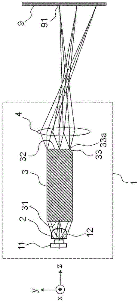
[0045] figure 1 It is a configuration diagram showing the configuration of the vehicle headlamp module 1 according to Embodiment 1 of the present invention. Such as figure 1 As shown, the vehicle headlamp module 1 according to Embodiment 1 includes a light source 11 , a light guide member 3 , and a projection lens 4 . Furthermore, the vehicle headlamp module 1 may include a light distribution control lens 2 . The light source 11 has a luminous area 12 . The light source 11 emits light for illuminating the front of the vehicle from the light emitting surface 12 . As the light source 11, an LED, an electroluminescent element, a semiconductor laser, or the like can be used. However, in the following description, the case where the light source 11 is an LED will be described. Hereinafter, the light source 11 is also called LED11.

[0046] The light distribution control lens 2 is a lens having positive refractive power. The light distribution control lens 2 sets, for example...

Embodiment approach 2

[0083] Figure 7 It is a configuration diagram showing the configuration of a vehicle headlamp module 10 according to Embodiment 2 of the present invention. right with figure 1 The same structural elements are denoted by the same reference numerals and their descriptions are omitted. and figure 1 The same structural elements are the light source 11 and the projection lens 4 . Like Embodiment 1, the light source 11 is also called LED11. Such as Figure 7 As shown, the vehicle headlamp module 10 according to Embodiment 2 includes LEDs 11 , a light guide member 300 , and a projection lens 4 . Furthermore, the vehicle headlamp module 10 may include a light distribution control lens 20 .

[0084] Unlike the first embodiment, the light distribution control lens 20 of the vehicle headlamp module 10 of the second embodiment is a cylindrical lens having curvature only in the y-axis direction. A "cylindrical lens" refers to a lens in which at least one surface of the lens is form...

Embodiment approach 3

[0099] Figure 9 It is a configuration diagram showing the configuration of a vehicle headlamp module 100 according to Embodiment 3 of the present invention. right with figure 1 The same structural elements are denoted by the same reference numerals and their descriptions are omitted. and figure 1 The same structural elements are the light source 11 , the light distribution control lens 2 , the light guide member 3 and the projection lens 4 . Like Embodiment 1, the light source 11 is also called LED11.

[0100] Such as Figure 9 As shown, the vehicle headlamp module 100 according to Embodiment 3 includes a light source 11 , a light guide member 3 , a projection lens 4 , a rotation mechanism 5 , and a control circuit 6 . The rotation mechanism 5 rotates the light guide member 3 and the projection lens 4 around the optical axis as a whole. "Integral" means to rotate simultaneously, and includes cases where the rotation angle of the light guide member 3 and the rotation ang...


PUM


Abstract

This headlight module for the vehicle is provided with a light source (11), a light guiding component (3), and a projection lens (4). The light source (11) emits light that forms illumination light. The light guiding component (3) has light emitted by the light source (11) incident thereto from an incident surface (31) as incident light and the incident light is superimposed by reflecting the incident light at side surfaces and emitted from an emission surface (32). The projection lens (4) projects the light emitted by the emission surface (32). The light guiding component (3) has an inclined surface (33) on a side surface. The brightness of part of a region is made brighter than other regions by superimposing incident light in which incident light has been reflected by the inclined surface (33) on incident light that has not been reflected by the inclined surface (33) in part of a region on the emission surface (32).

Description

technical field [0001] The present invention relates to a vehicle headlamp module and a vehicle headlamp device that illuminate the front of a vehicle body. Background technique [0002] from suppressing CO 2 From the viewpoint of reducing the burden on the environment such as emissions and fuel consumption, energy saving of vehicles is desired. Along with this, there is also a demand for downsizing and weight reduction of vehicle headlamps, and power saving is also required. Therefore, it is desired to employ a semiconductor light source having a higher luminous efficiency than conventional halogen bulbs as a light source for vehicle headlamps. A "semiconductor light source" means, for example, a light emitting diode (hereinafter referred to as LED (Light Emitting Diode).), a laser diode (LD), or the like. A "vehicle headlamp" refers to a lighting device mounted on a conveyance machine or the like, and used to improve the driver's visibility and the performance of being ...

Claims


Application Information

Patent Timeline
Patent Type & Authority Applications(China)
IPC IPC(8): F21S8/10F21S8/12F21W101/10F21Y115/10
CPCF21S41/143F21S41/147F21S41/285F21S41/24F21S41/255F21S41/635F21S45/10B62J6/026B62J6/024
Inventor 诹访胜重大岛律也桑田宗晴小岛邦子
Owner MITSUBISHI ELECTRIC CORP
Why Eureka
Try Eureka