Modular furniture assembly with dual coupling mechanisms

Inactive Publication Date: 2016-06-23
THE LOVESAC CORP
View PDF0 Cites 40 Cited by
  • Summary
  • Abstract
  • Description
  • Claims
  • Application Information

AI Technical Summary

Benefits of technology

[0013]Another aspect of the present invention relates to a modular furniture assembly including a first member and a second member. Either or both of the first member and the second member may include a fabric or other cover over a body (e.g., which may optionally be foam), where the body includes a rigid core. A coupling mechanism that is a magnetically attractive coupling mechanism and/or a mechanical coupling mechanism may be provided for selectively, removably coupling the first member to the second member. The coupling mechanism may include anti-tenting characteristics to prevent the fabric or other cover material of the first member and/or the second member from “tenting” as a first member and second member are pulled apart from one another. For example, the coupling mechanism may include a first member portion on or within the first member, and a second member portion disposed on or within the second member. The first member portion may be tethered to the rigid core of the first member. The second member portion may be tethered to the rigid core of the second member. Such a rigid core may include a rigid board or other relatively inflexible structure of the body that can serve as an anchor to which the coupling mechanism portions may be tethered. Such tethering reduces, minimizes or prevents tenting of the fabric or other cover(s) as the first member portion (e.g., a magnet, attracted member, VELCRO panel, etc.) is pulled relative to the remainder of the first member, or as the second member portion (e.g., a magnet, attracted member, VELCRO panel, etc.) is pulled relative to the remainder of the se

Problems solved by technology

In addition, many traditional couches and other furniture items cannot be moved into tight areas of a home or apartment complex, including, for example, basements, narrow hallways, or upstairs rooms.
However, the connections between modular assembl

Method used


Image

  • Modular furniture assembly with dual coupling mechanisms
  • Modular furniture assembly with dual coupling mechanisms
  • Modular furniture assembly with dual coupling mechanisms

Examples


Embodiment Construction

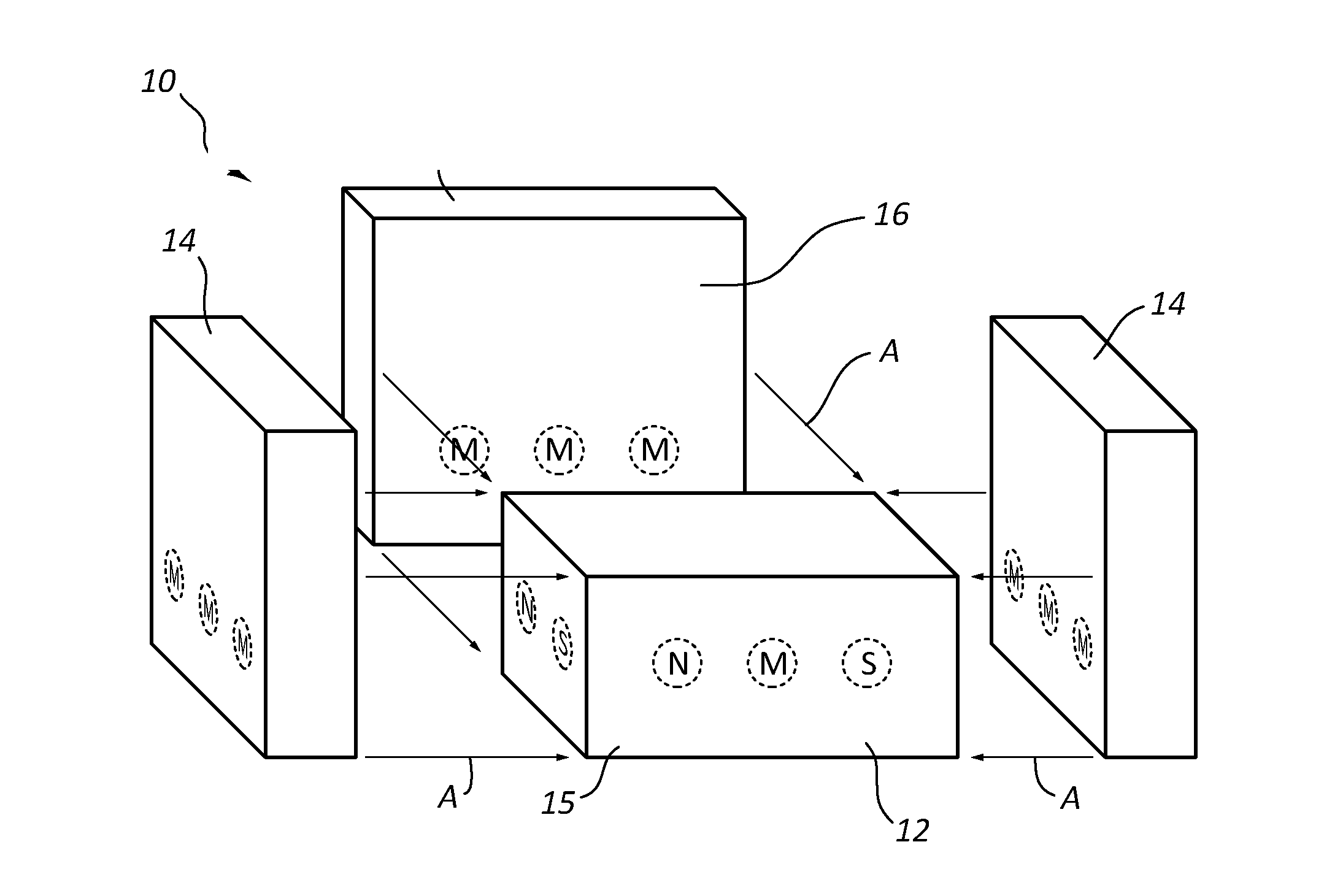
[0064]FIGS. 1A-5D are schematic representations of a modular furniture assembly with a magnetically attractive coupling assembly (also referred to herein as a magnetic coupling assembly), illustrating how the magnets and / or attracted members may be arranged so as to allow selective, removable coupling of the various members in variously configured modular furniture assemblies.

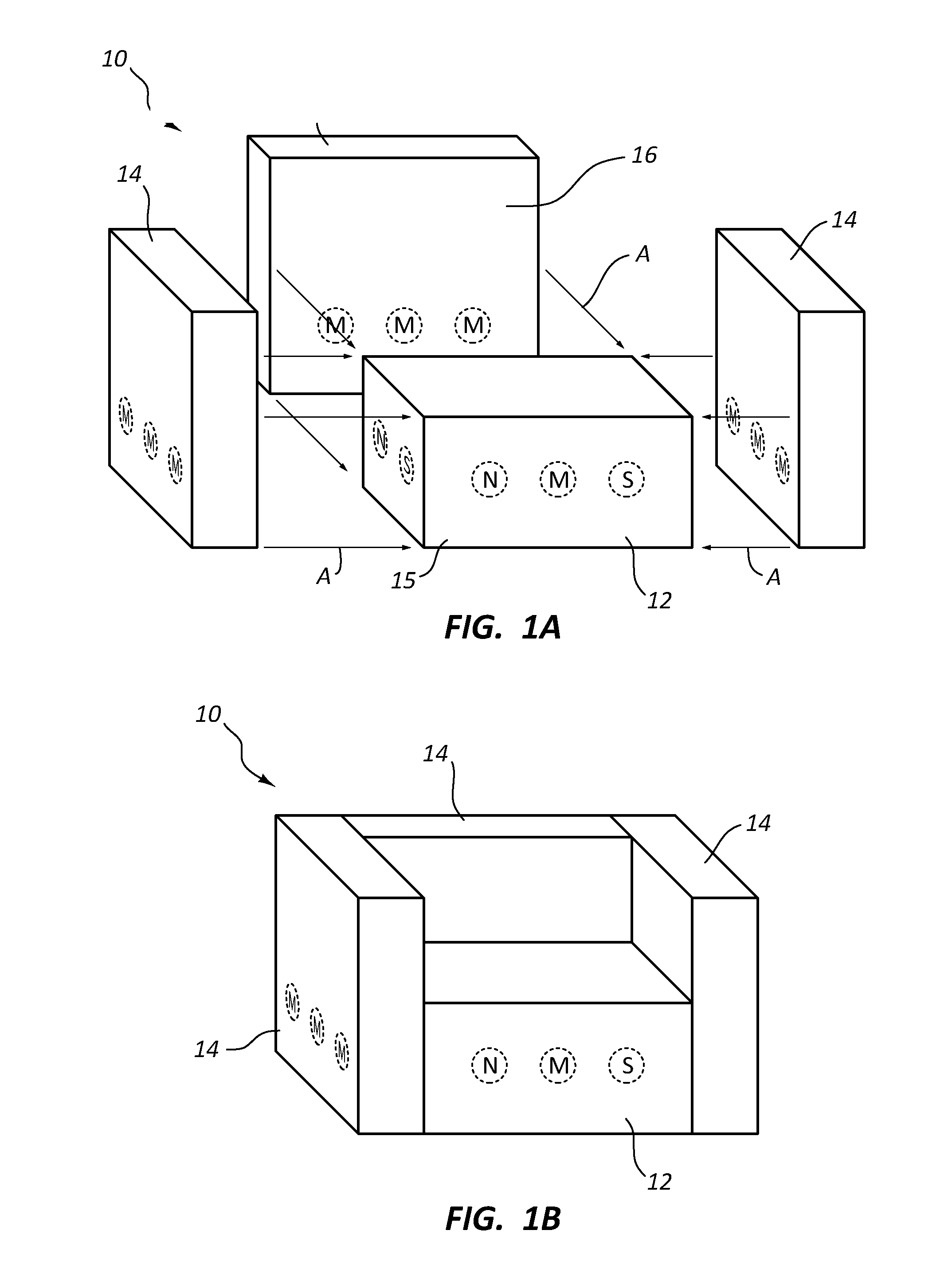
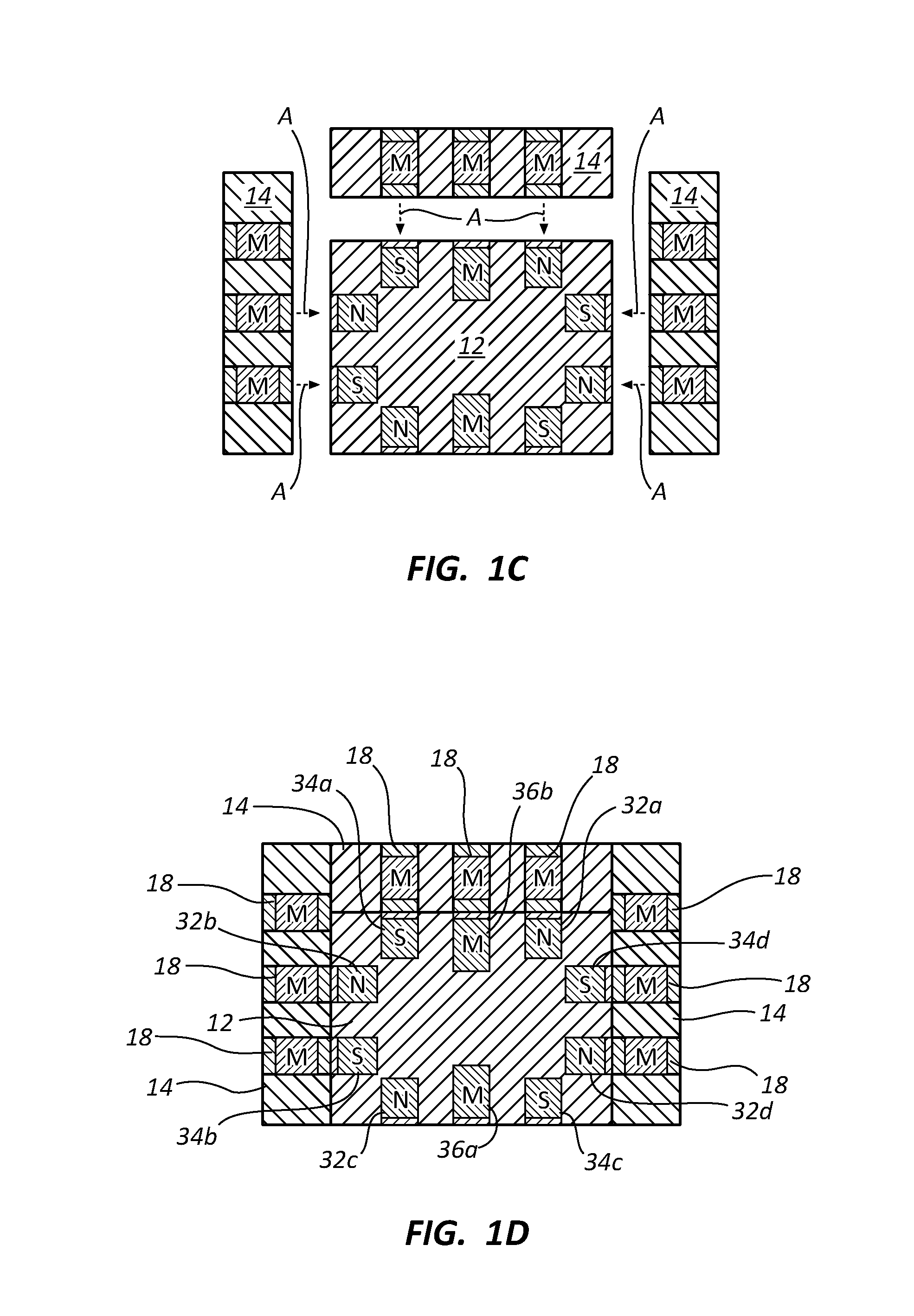
[0065]FIG. 1A shows an assembly 10 with a magnetic coupling assembly, while FIG. 1B is a view of the furniture assembly 10 of FIG. 1A in an assembled configuration. FIGS. 1C and 1D show possible positions of magnets and / or attracted members in the base member and transverse members for the assembly 10 of FIGS. 1A and 1B.

[0066]Modular furniture assembly 10 comprises a base member 12 and three transverse members 14 that are selectively, removably coupled by a magnetic coupling assembly to base member 12. The magnetic coupling assembly is comprised of at least one magnet and at least one attracted member, e.g., an...


PUM


Abstract

A modular furniture assembly comprising first and second members (e.g., base and transverse member) may have convenient dual coupling mechanisms, for example, a magnetic coupling mechanism and a mechanical (e.g., hook and loop) coupling mechanism. The first member and/or second member may include a fabric or other cover over a foam or other body (e.g., fabric over foam, or other cover over a skeleton). Either or both members may include a rigid core (e.g., a board, skeleton, etc.). The coupling mechanisms may be such as to not detract from any soft, cushioned characteristics of a fabric over foam construction, if such is provided. The coupling structure in the first member and/or the second member may be tethered to the rigid core of the particular member to reduce tenting of the fabric or other cover of the first member and/or the second member as the tethered coupling structure is pulled.

Description

1. CROSS-REFERENCE TO RELATED APPLICATIONS[0001]This application is a continuation-in-part of U.S. patent application Ser. No. 14 / 332,705, filed Jul. 16, 2014, entitled MOUNTING PLATFORM FOR MODULAR FURNITURE ASSEMBLY, which is a continuation of U.S. patent application Ser. No. 13 / 164,721, filed Jun. 20, 2011, entitled MOUNTING PLATFORM FOR MODULAR FURNITURE ASSEMBLY, now U.S. Pat. No. 8,783,778, which is a continuation-in-part of U.S. patent application Ser. No. 12 / 484,931, filed Jun. 15, 2009, entitled MODULAR FURNITURE ASSEMBLY, now U.S. Pat. No. 7,963,612, which is a continuation-in-part of U.S. patent application Ser. No. 11 / 449,074, filed Jun. 8, 2006, entitled MODULAR FURNITURE ASSEMBLY, now U.S. Pat. No. 7,547,073, which is a continuation-in-part of U.S. patent application Ser. No. 11 / 149,913, filed Jun. 10, 2005, entitled MODULAR FURNITURE ASSEMBLY, now U.S. Pat. No. 7,213,885. Each of the foregoing applications is incorporated herein, in its entirety, by reference.[0002]Th...

Claims


Application Information

Patent Timeline
IPC IPC(8): A47C4/02A47C7/20A47C7/18F16B1/00F16B12/00
CPCA47C4/028F16B1/00F16B12/00F16B2001/0028A47C7/20F16B2001/0035A47C7/18A47C13/005A47C17/045Y10T29/49826Y10T403/7164Y10T403/7176A47C15/002A47C31/003A47C7/628A47C7/626F16B2200/81F16B2200/83
Inventor NELSON, SHAWN D.UNDERWOOD, DAVID M.PEARSON, SPENCERKOSTEK, CHELSEAKUCHLER, BRIAN
Owner THE LOVESAC CORP
Why Eureka
Try Eureka