Tension management apparatus for cable-driven transmission

a technology of tension management and cable drive, which is applied in the direction of mechanical equipment, surgical forceps, gearing, etc., can solve the problems of cable driven transmission system slack, lack of complete determinism of driven pulley rotational position, etc., and achieve the effect of reducing slack

Active Publication Date: 2018-03-22
RGT UNIV OF MICHIGAN
View PDF11 Cites 19 Cited by
  • Summary
  • Abstract
  • Description
  • Claims
  • Application Information

AI Technical Summary

Benefits of technology

[0016]Described herein are apparatuses and methods that compensate for slack in a cable of a transmission system having at least one pulley. In particular, these apparatuses and methods may compensate for slack in the transmission system by applying a tension to a cable, or equivalently removing slack from the cable, that is related to the rotation of a pulley that is operating on the cable. The slack-compensating pulleys described herein, and apparatuses including them, may lengthen the path taken by a part of a cable that would otherwise be slack, by increasing the wrap angle of the cable on the pulley body. The slack-compensating pulley apparatuses described herein may generally include a pulley body that includes a surface on which a cable may wrap at a wrap angle, and a slack take-up surface that rotates with the pulley body and applies tension to the cable when the pulley body rotates. The slack take-up surface may be part of or attached to a support that extends from the pulley body and rotates with the pulley body. Driving the slack take-up surface against a length of the cable that extends off of the pulley body when the pulley body is rotated increases the wrap angle of the cable around the pulley body and can reduce or eliminate slack in this portion of the cable. The slack-compensating pulleys described herein may include one or more than one (e.g., two, three, etc., but preferably two) slack take-up surfaces. Thus, a slack-compensating pulley may include one or more slack take-up surfaces that rotate with the pulley body of the slack-compensating pulley and deflect a portion of the cable to lengthen the cable path, and therefore increase the wrap angle of the cable around the pulley body, when the slack-compensating pulley rotates in a first direction about an axis of rotation of the slack-compensating pulley, but not when rotating in the opposite direction. When the slack-compensating pulley is rotated in the opposite direction, the slack take-up surface may be withdrawn from the cable, reducing the wrap angle of the cable around the pulley body and reducing the path length taken by the cable off of the pulley body.

Problems solved by technology

Thus, the driven pulley rotation is not fully determined or secure.
This lack of complete determinism of the driven pulley rotational position (which is sometimes also referred to as backlash, play, or slop) is a major drawback of cable driven transmission systems.
Nevertheless, the above described problem of cable slack applies in this case as well.
Unfortunately, when multiple cables (which may equivalently be wires, ropes, strands, filaments, lines, actuating cables, tendons, pull-wires, etc.) are used, bending in one direction, e.g., by pulling on one or more of the cables, may result in slack forming in the other cable(s).
This slack may negatively impact the operation of the device, particularly when pulling / pushing the cables to control bending of the member, resulting in non-deterministic or unpredictable motion characterized by compliance or backlash.
In all these cases, the end effector joint poses several design challenges.
However, this design is inherently prone to problems associated with slack generation in the cables that are used for driving the end effector rotation discussed above.

Method used


Image

  • Tension management apparatus for cable-driven transmission
  • Tension management apparatus for cable-driven transmission
  • Tension management apparatus for cable-driven transmission

Examples


Embodiment Construction

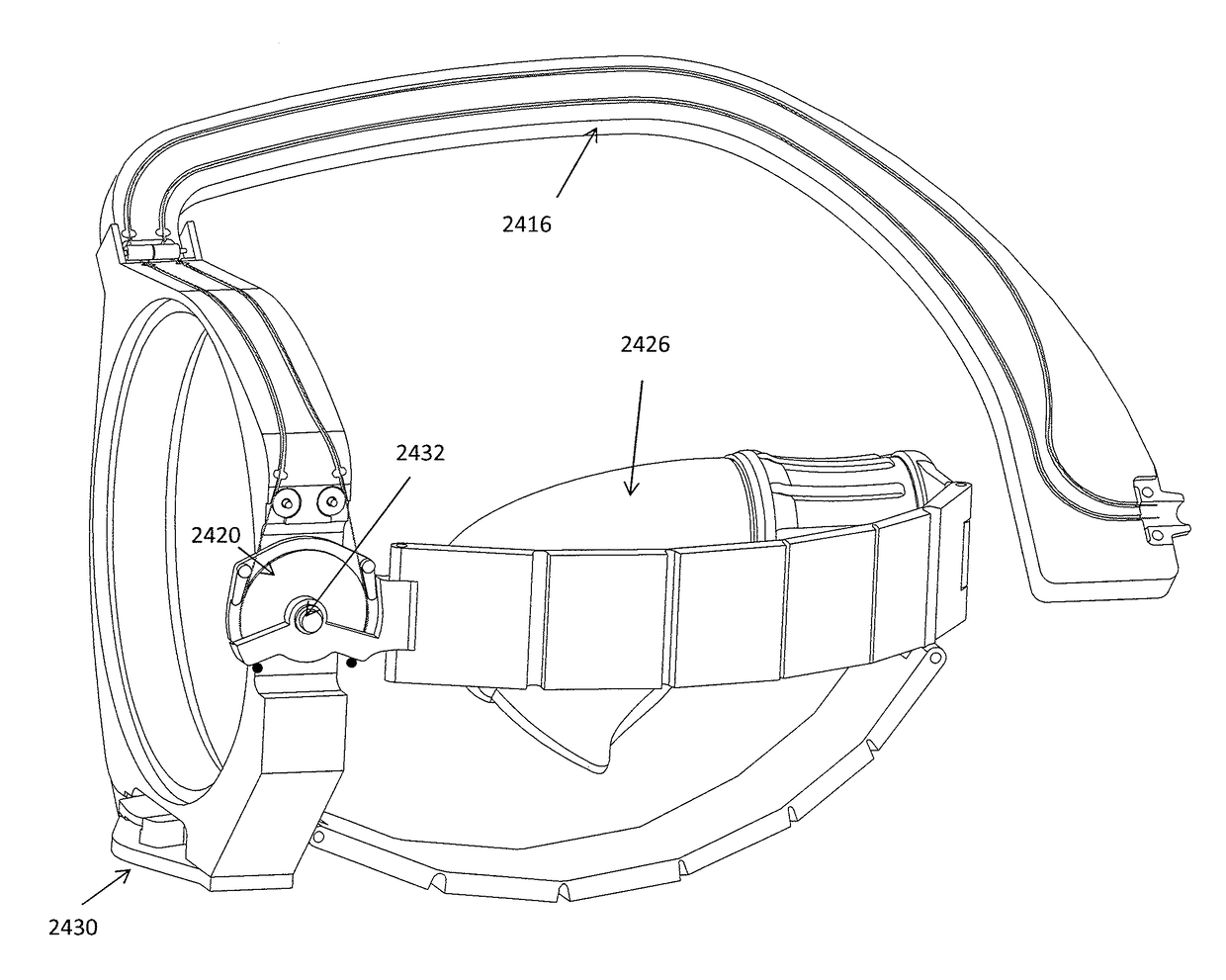
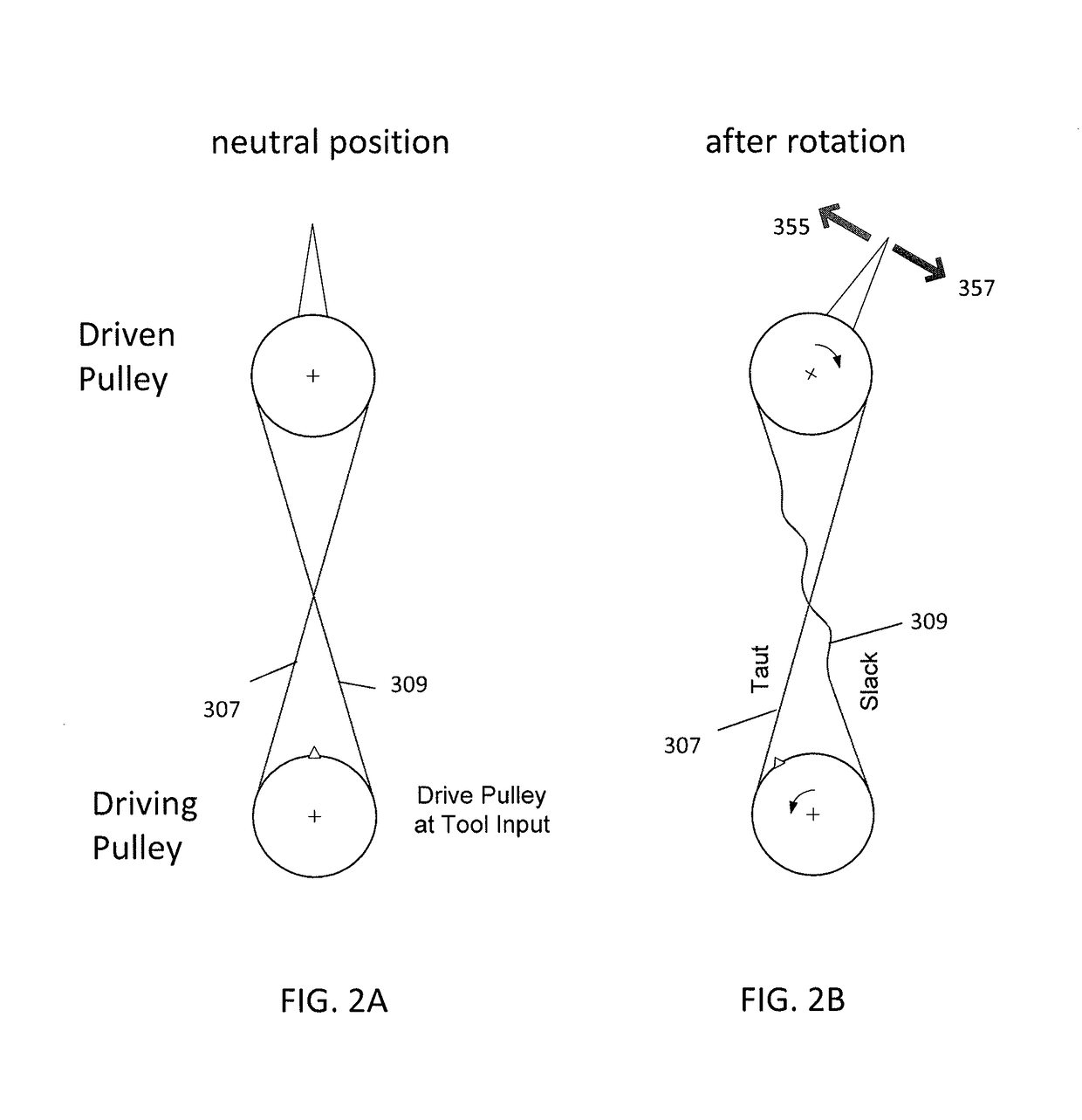
[0097]In general, described herein are slack compensating apparatuses for cable transmission systems, slack compensating pulleys, device (including in particular minimal access surgical tools) including a slack compensating transmission, and methods of operating them. In general, a slack-compensating pulley may have a pulley body with one or more (e.g., two) supports extending beyond the pulley body. The support(s) may include one or more slack take-up surfaces on them. The pulley body, support(s) and slack take-up surface(s) are coupled so that they rotate together about an axis of rotation, and rotation of the apparatus in a first direction will drive at least one of the slack take-up surfaces against a cable wound on the pulley body to reduce or remove slack from a portion of the cable leaving the pulley body. Driving the slack take-up surface against the cable increases the path length taken by the portion of the cable leaving the pulley body and also increases the wrap angle of...


PUM


Abstract

Slack-compensating pulleys, transmission systems including slack-compensating pulleys, and methods of operating these. In general, slack-compensating pulleys include a pulley body onto which a cable can wind, and one or more (e.g., two) slack take-up surfaces that rotate with the pulley body that are configured to remove slack form an outgoing length of cable by increasing the cable path length and wrap angle. In particular, described herein are minimal access tools having slack-compensating transmissions.

Description

CROSS REFERENCE TO RELATED APPLICATIONS[0001]This application claims priority to U.S. Provisional Patent Application No. 62 / 142,980, filed on Apr. 3, 2015, titled “TENSION MANAGEMENT APPARATUS FOR CABLE-DRIVEN TRANSMISSION” which is herein incorporate by reference in its entirety.[0002]This application may be related to U.S. patent application Ser. No. 14 / 166,503, filed on Jan. 28, 2014, and titled “MINIMAL ACCESS TOOL,” Publication No. US-2014-0142595-A1, which is a continuation of U.S. patent application Ser. No. 12 / 937,523, filed on Apr. 13, 2009, titled “MINIMAL ACCESS TOOL,” now U.S. Pat. No. 8,668,702, each of which is herein incorporated by reference in its entirety.INCORPORATION BY REFERENCE[0003]All publications and patent applications mentioned in this specification are herein incorporated by reference in their entirety to the same extent as if each individual publication or patent application was specifically and individually indicated to be incorporated by reference.FIEL...

Claims


Application Information

Patent Timeline
Patent Type & Authority Applications(United States)
IPC IPC(8): F16H19/06
CPCF16H19/0672A61B1/3132A61B34/71A61B1/0057A61B2034/715A61B17/29A61B2017/2927A61B2017/2929A61B2017/00314A61B2017/291A61B2017/00323A61B2034/306
Inventor AWTAR, SHORYA
Owner RGT UNIV OF MICHIGAN
Why Eureka
Try Eureka