Eureka AIR delivers breakthrough ideas for toughest innovation challenges, trusted by R&D personnel around the world.

System and Method for Processing Fluid in a Fluidic Cartridge

Active Publication Date: 2016-06-23
ATLAS GENETICS
View PDF1 Cites 13 Cited by
  • Summary
  • Abstract
  • Description
  • Claims
  • Application Information

AI Technical Summary

Benefits of technology

The present invention is a valve system in a fluidic cartridge for measuring liquid samples. The system has an inlet valve, an outlet valve, and a bypass channel. The valve system allows for the evacuation of excess liquid sample when the outlet valve is closed, resulting in a metered volume of liquid sample in the fluid pathway between the inlet valve and the downstream sample processing region. This design allows for sample processing to occur while keeping the sample in the same position in the cartridge.

Problems solved by technology

Sample preparation and analysis presents many logistical problems.
This approach is inadequate.
Firstly, there is a significant risk that a sample is lost in transit or mismatched with the wrong patient.
Moreover, whilst recent developments in technology have reduced the overall time taken to conduct the test, the delay involved in sending the sample to a laboratory is unsatisfactory.
Nevertheless, analytical systems of the kind found in laboratories are complex and it is often difficult to provide sufficient amounts of pure targets from source samples to reliably perform downstream analytical assays.
This typically prohibits local GP surgeries from being able to carry out such tests on site.
However, it has been found that handling a sample in a microfluidics device can be very difficult.
In such small channels as are found on a conventional LOC, it is difficult to apply external forces to move the sample from one site to another to perform different actions on the sample.
There is also a limit to the complexity of a LOC device which operates purely using capillary action.
Furthermore, owing to the small sample sizes of LOC's, the devices have reduced sensitivity and the probability of a target being present in the sample is thus reduced.
It is particularly important in LOC type cartridges where multiple fluid sample preparation steps are performed within the cartridge that the tolerances of the channel and chambers in the sample processing region are not allowed to stack up prior to processing and analysis of the fluid sample as this may lead to fairly large errors in the calculated amount of fluid required to fill the PCR chamber and subsequently be delivered to the detection chambers.
This means that over-filling the PCR chamber and allowing an excessive amount of fluid sample to flow past the sample processing region may lead to a lack of reagents remaining in the PCR chamber.
Under-filling the PCR chamber by even a small amount may lead to air pockets in the PCR chamber which in turn may lead to unstable thermocycling.
However, even slightly overfilling the PCR chamber leads to unprocessed fluid downstream of the PCR chamber which may then dilute processed fluid sample as it is moved from the PCR chamber to the detection chambers.

Method used


Image

  • System and Method for Processing Fluid in a Fluidic Cartridge
  • System and Method for Processing Fluid in a Fluidic Cartridge
  • System and Method for Processing Fluid in a Fluidic Cartridge

Examples


first embodiment

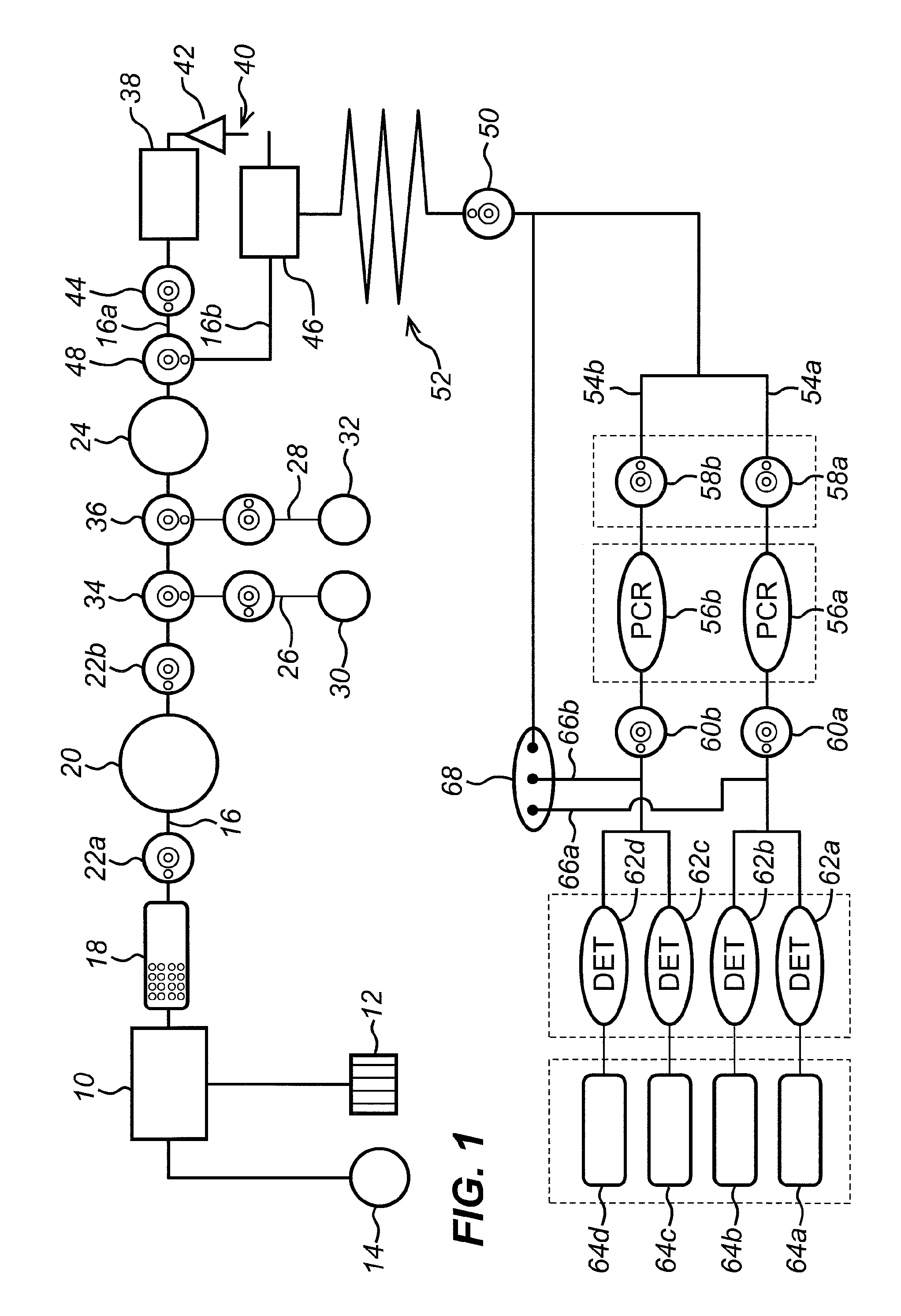
[0229]FIG. 16 shows a valve system according to the invention for metering a liquid sample. The valve system C100 comprises a fluid pathway C110 for passing fluid from an upstream end to a downstream end, a sample processing chamber C102 within the fluid pathway, having an inlet valve C101 upstream of the sample processing chamber C102 and an outlet valve C103 downstream of the sample processing chamber C102. The sample processing chamber may, for example, be a nucleic acid amplification chamber 58a-b described above in respect of the exemplary cartridge, although other chambers are also possible. A downstream sample processing region may be provided at the downstream end of the fluid pathway. In the exemplary cartridge, the downstream sample processing region may be target chamber C104, which is located along the fluid pathway downstream of the outlet valve C103. Again, the target chamber may, for example, be a detection chamber 64a-d described above in respect of the exemplary car...

second embodiment

[0252]Thus, FIG. 20 shows a valve system according to the invention for expelling a liquid sample from sub-system such as a sample processing region (not shown). The valve system C500 comprises a fluid pathway C510 for passing fluid from an upstream end to a downstream end, an outlet valve C503 downstream of the sample processing region (not shown), and a target chamber C504 located along the fluid pathway downstream of the outlet valve C503. The target chamber may, for example, be a detection chamber 64a-d described above in respect of the exemplary cartridge, although other chambers are also possible, depending on the particular sample processing region. Irrespective of the purpose to which the target chamber is put, the target chamber is a chamber to which a volume of a liquid sample is to be delivered, once the sample has exited the sample processing region.

[0253]A bypass channel C505 is coupled to the fluid pathway between the outlet valve C503 and the target chamber C504. The ...


PUM

PropertyMeasurementUnit
Forceaaaaaaaaaa
Pressureaaaaaaaaaa
Volumeaaaaaaaaaa

Abstract

A system and method for processing fluid in a fluidic cartridge is provided. The system comprises a fluid pathway for passing a liquid sample therethrough from an upstream end to a downstream end, a sample processing chamber within the fluid pathway having an inlet valve upstream of the sample processing chamber, a downstream sample processing region within the fluid pathway downstream of the outlet valve and a bypass channel coupled to the fluid pathway at a junction between the outlet valve and the downstream sample processing region, the valve system configured such that surplus liquid downstream of the outlet valve may be evacuated through the bypass channel when the outlet valve is closed, thereby leaving a metered volume of liquid sample between the inlet valve and the downstream sample processing region.

Description

FIELD[0001]The present invention relates to valve systems and corresponding methods for processing a liquid sample in a fluidic cartridge. More specifically, the present invention relates to a metering system for delivering a volume of liquid sample and a system for expelling excess liquid sample.BACKGROUND[0002]Sample preparation and analysis presents many logistical problems. Conventionally, many medical samples (such as blood, saliva, urine and swab eluate) are provided to a doctor, for example a general practitioner doctor (GP) or a principle care physician (PCP), in a local surgery without the equipment necessary to analyse the sample. Hence, the sample must be sent to a laboratory where the sample is analysed. The test results must then be collated and returned to the GP to analyse the results and make a diagnosis. This approach is inadequate. Firstly, there is a significant risk that a sample is lost in transit or mismatched with the wrong patient. Moreover, whilst recent dev...

Claims


Application Information

Patent Timeline
IPC IPC(8): B01L3/00C12Q1/68
CPCB01L3/502C12Q1/6844B01L2200/0605B01L2400/0487B01L2400/0622B01L2300/0861B01L2300/12B01L2400/0633B01L3/50273B01L3/502738G01N35/1097B01L2300/0816B01L2400/0655B01L3/502723G01N35/1016
Inventor TAYLOR, JAY KENDALLARLETT, BEN
Owner ATLAS GENETICS
Why Eureka
Eureka Blog
Learn More