Controlled alternating flow direction for enhanced conformance

Active Publication Date: 2016-06-23
MAERSK OLIE & GAS AS
View PDF14 Cites 1 Cited by
  • Summary
  • Abstract
  • Description
  • Claims
  • Application Information

AI Technical Summary

Benefits of technology

[0035]The ratio, e.g. molar ratio, of the second composition to the first composition may be less than or equal to 1:1, e.g. may be less than 1:1. In one embodiment, the molar ratio, of the second composition to the first composition may be in the range of 0.5:1-1:1, e.g. 0.8:1-1:1. By such provision, the amount of unreacted reactants in the second composition may be minimised or reduced. This may be particularly advantageous if the second composition is not designed or configured to degrade and/or disintegrate under the conditions in the first region.
[0036]The first composition may have a viscosity greater than the viscosity of the second composition. By such provision, injection of the second composition may displace at least a portion of the displa

Problems solved by technology

When two or more chemicals are required to react and plug a high-permeability zone, the reaction may also cause plugging of

Method used


Image

  • Controlled alternating flow direction for enhanced conformance
  • Controlled alternating flow direction for enhanced conformance
  • Controlled alternating flow direction for enhanced conformance

Examples


Example

DETAILED DESCRIPTION OF THE DRAWINGS

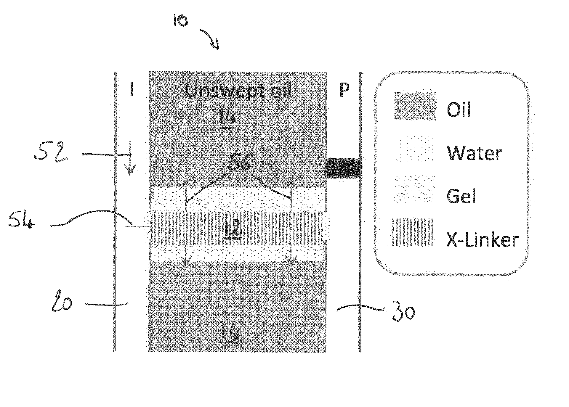
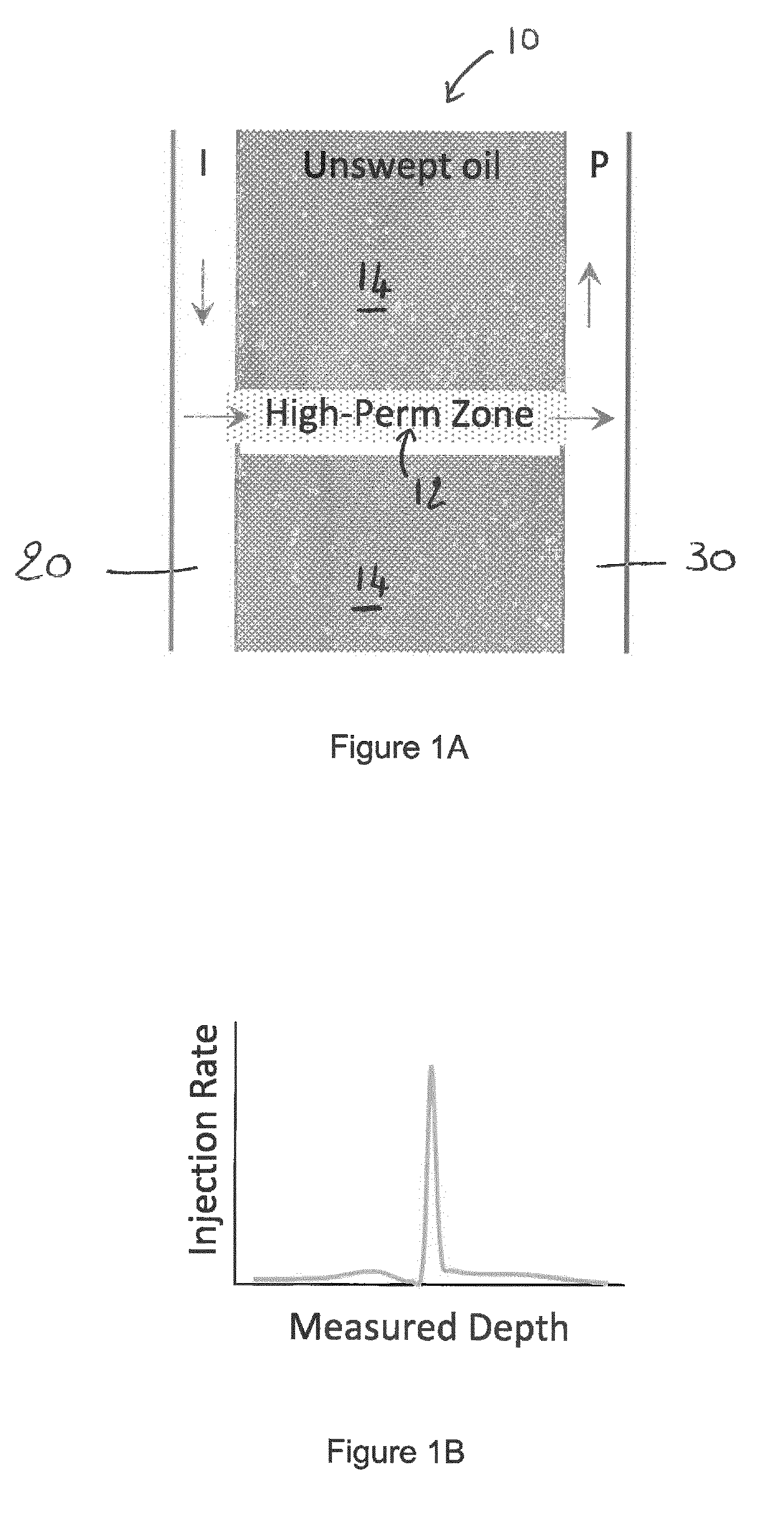
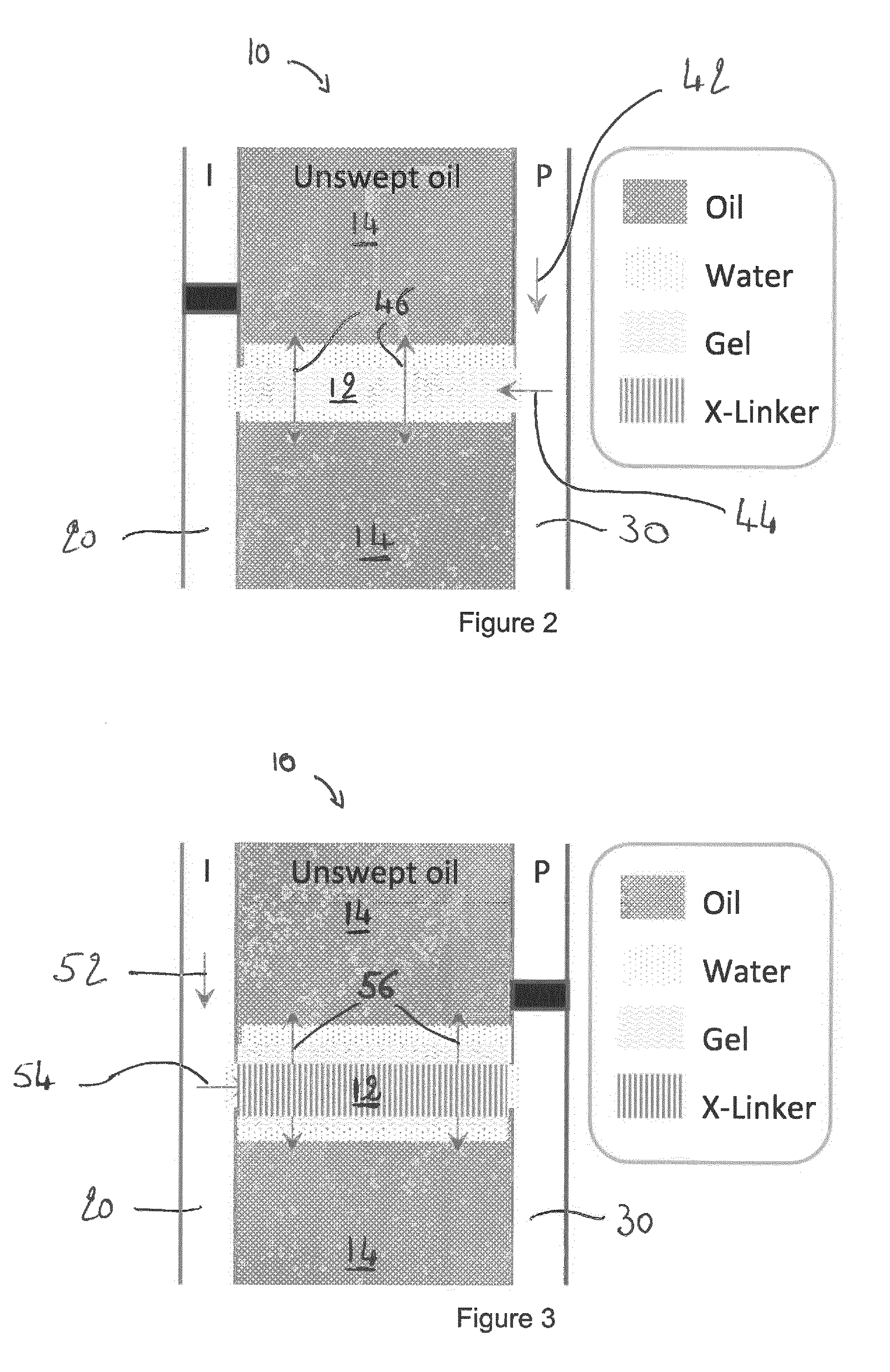
[0092]FIG. 1A is a schematic cross-sectional view of a formation 10 comprising a first region 12 of high permeability and second regions 14 of low permeability.

[0093]The method according to the present invention aims to reduce the permeability in the first region 12 of formation 10.

[0094]An injection well 20 and a production well 30 are provided on either side of the formation 10, and in this embodiment on either side of the first region 12. It will be appreciated, however, that the precise disposition to the injection well 20 and production well 30 may be selected depending on the particular profile and / or characteristics of each particular formation 10 being produced.

[0095]As shown by the arrows on FIG. 1A, should Enhanced Oil Recovery techniques be implemented in the formation of FIG. 1A, the injected EOR fluid would preferentially enter and travel through the formation through the first region 12 of high permeability, thus achieving unsatisfac...


PUM


Abstract

A method for reducing permeability in a first region 12 of a formation 10, comprises injecting a first composition in the first region 12 from a first location 30 near or and/or adjacent the first region 12; and injecting a second composition in the first region 12 from a second location 20 near or and/or adjacent the first region 12; wherein the first composition and the second composition are configured to react so as to form a reaction product 60 capable of reducing the permeability in at least a portion of the first region 12.

Description

FIELD OF THE INVENTION[0001]The present invention relates to a method for reducing the permeability of a region of a subterranean formation, and in particular, though not exclusively, to a method for at least partially plugging a high-permeability region of a subterranean formation for subsequent enhanced oil recovery by water, gas, or chemical flooding.BACKGROUND TO THE INVENTION[0002]Water flooding as an oil recovery technique has been in use since 1890 when operators in the US realised that water entering the productive reservoir formation was stimulating production. In some cases, water is supplied from an adjacent connected aquifer to push the oil towards the producing wells. In situations where there is no aquifer support, water is typically pumped into the reservoir through dedicated injection wells. The water phase replaces the oil and gas in the reservoir and thereby serves to maintain pressure. Recovery factors from water flooding vary from 1-2% in heavy oil reservoirs up ...

Claims


Application Information

Patent Timeline
IPC IPC(8): E21B33/138E21B43/16
CPCE21B43/16E21B33/138E21B43/20
Inventor BENNETZEN, MARTINMOGENSEN, KRISTIAN
Owner MAERSK OLIE & GAS AS
Why Eureka
Try Eureka