
Pressure bearing fluid mixing apparatus

A technology of fluid mixing and mixed flow, applied in fluid mixers, mixers, lamination components, etc., can solve the problems of long mixing reaction time, reduced mixing efficiency, large volume and insufficient compactness, and avoid by-products and materials. Degradation, increasing heat exchange surface area, reliable and compact structure

Pending Publication Date: 2019-11-12
欧志安
View PDF0 Cites 1 Cited by
  • Summary
  • Abstract
  • Description
  • Claims
  • Application Information

AI Technical Summary

Problems solved by technology

The application of traditional kettle-type mixing reactors is usually composed of feeding, heat transfer, transmission, stirring and sealing. Its bulky size and large amount of single raw material addition lead to long mixing reaction time and greatly reduced mixing efficiency. The added materials contain flammable, explosive, poisonous, corrosive media and other characteristics, which are extremely dangerous. Moreover, in order to stably control the reaction temperature of the mixture, it is usually necessary to equip corresponding cooling and heat exchange devices, which makes The structure of the whole mixing equipment is not compact enough, and the heat exchange surface area is small, resulting in low heat exchange efficiency, which makes it inconvenient to carry out related operations and easily leads to safety accidents
Therefore, the traditional mixing device has the disadvantages of low stirring efficiency, high risk, not safe enough, large size and not compact enough, and inability to effectively control the reaction temperature. Effective solutions need to be proposed to solve them

Method used


Image

  • Pressure bearing fluid mixing apparatus
  • Pressure bearing fluid mixing apparatus
  • Pressure bearing fluid mixing apparatus

Examples


Embodiment Construction

[0047] This part will describe the specific embodiment of the present invention in detail, and the preferred embodiment of the present invention is shown in the accompanying drawings. Each technical feature and overall technical solution of the invention, but it should not be understood as a limitation on the protection scope of the present invention.

[0048] In the description of the technical solution of the present invention, it should be understood that the orientation descriptions, such as the orientation or positional relationship indicated by up, down, front, back, left, right, etc., are based on the orientation or positional relationship shown in the drawings, It is only for the convenience of describing the present invention and simplifying the description, but does not indicate or imply that the device or element referred to must have a specific orientation, be constructed and operated in a specific orientation, and thus should not be construed as limiting the presen...


PUM


Abstract

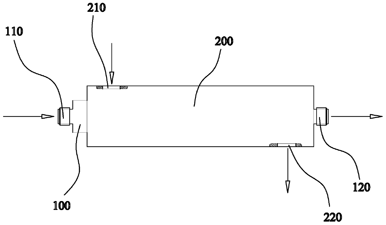
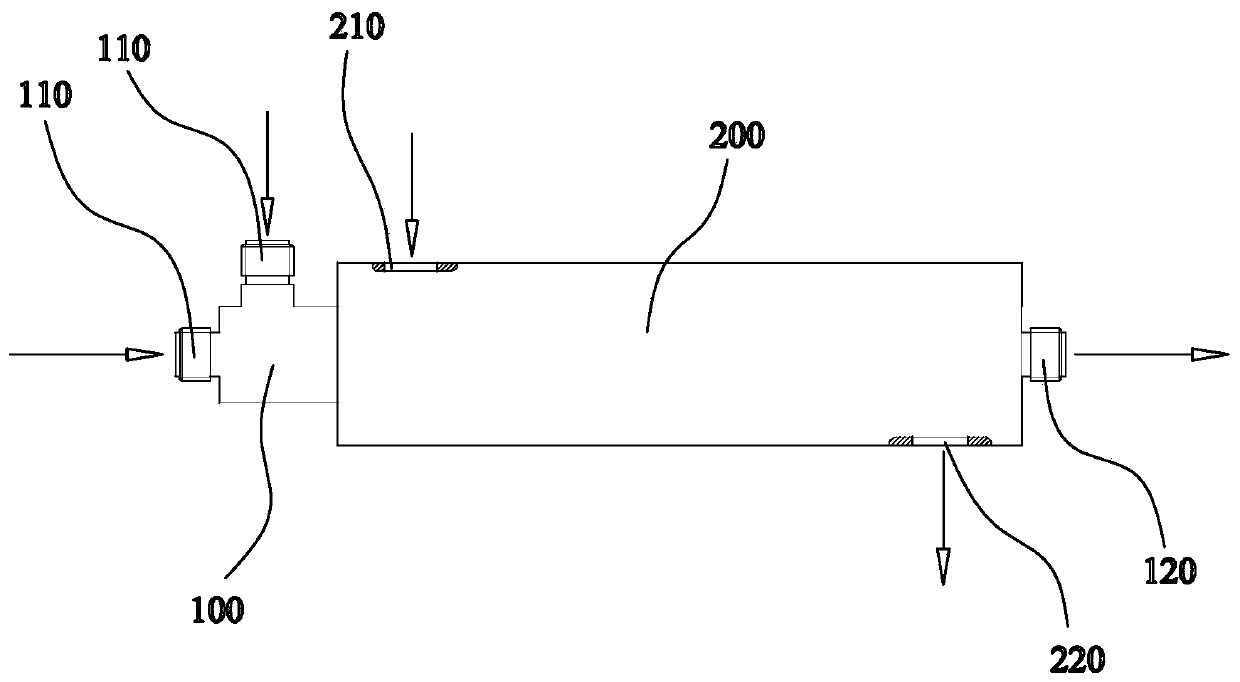
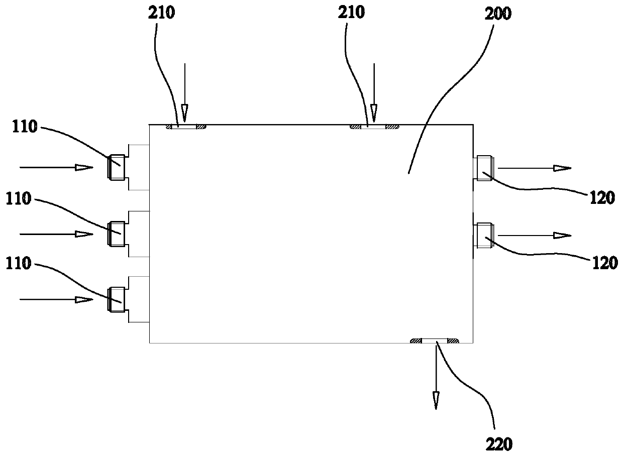
The invention discloses a pressure bearing fluid mixing apparatus, which comprises an inner bushing and an outer bushing, wherein a first channel is arranged in the inner bushing, and comprises a plurality of unit channels, the adjacent unit channels are communicated, a flow blocking member is fixed on the unit channel, the inner bushing is provided with a plurality of first inlets and a pluralityof first outlets, a second channel is arranged in the outer bushing, the outer bushing is provided with a plurality of second inlets and a plurality of second outlets, and the inner bushing is fixedon the second channel. According to the present invention, by organically combining the inner bushing and the outer bushing, the efficient mixing and heat exchange effect of different fluids is achieved; and compared with the conventional fluid stirring device, the technical scheme of the present invention has advantages of continuous and stable mixing reaction, safety and high efficiency.

Description

technical field [0001] The invention relates to the technical field of food and chemical fluid mixing, in particular to a pressurized fluid mixing device. Background technique [0002] my country is a big country in chemical industry. Every year, a large number of enterprises and chemical factories need to mix or mix a large amount of fluids to synthesize the required products. The application of traditional kettle-type mixing reactors is usually composed of feeding, heat transfer, transmission, stirring and sealing. Its bulky size and large amount of single raw material addition lead to long mixing reaction time and greatly reduced mixing efficiency. The added materials contain flammable, explosive, poisonous, corrosive media and other characteristics, which are extremely dangerous. Moreover, in order to stably control the reaction temperature of the mixture, it is usually necessary to equip corresponding cooling and heat exchange devices, which makes The structure of the ...

Claims


Application Information

Patent Timeline
IPC IPC(8): B01F5/06B01F15/06B01J19/24C07C67/14C07C69/747F28D7/10
CPCB01J19/244B01J19/2415B01J19/0013C07C67/14F28D7/10B01J2219/00076B01F25/431B01F25/435B01F2035/98B01F35/93C07C69/747B01J2219/0263B01J2219/0277B01J2219/0295B01F25/4323B01J19/2405B01F2101/2204B01F2101/06B01F25/4319B01F25/431971B01F2215/0431F28F3/12
Inventor 欧志安欧雪莹
Owner 欧志安
Learn More