Novel urea mixer

A technology of mixer and urea, which is applied in the field of power machinery, can solve the problems of higher nozzle atomization capacity, increased nozzle manufacturing cost, and increased nozzle manufacturing difficulty, so as to optimize structural layout, reduce production materials and costs, reduce The effect of small volume

Active Publication Date: 2016-11-16
GUANGXI YUCHAI MASCH CO LTD
View PDF7 Cites 1 Cited by
  • Summary
  • Abstract
  • Description
  • Claims
  • Application Information

AI Technical Summary

Problems solved by technology

[0004] 1. Since there is no structure that can promote the mixing of urea and exhaust gas, the entire injection system has higher requirements on the atomization ability of the nozzle, which makes the manufacture of the nozzle more difficult and increases the manufacturing cost of the nozzle;
[0005] 2. In order to make the mixing time of urea and exhaust gas fully mixed, the length of the mixer will be designed to be very long. Moreover, because urea i

Method used


Image

  • Novel urea mixer
  • Novel urea mixer
  • Novel urea mixer

Examples


Embodiment Construction

[0024] The present invention will be further described below in conjunction with the specific embodiments in the accompanying drawings.

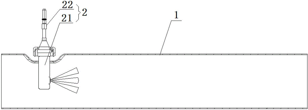
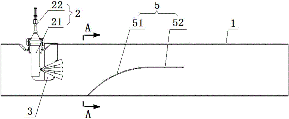
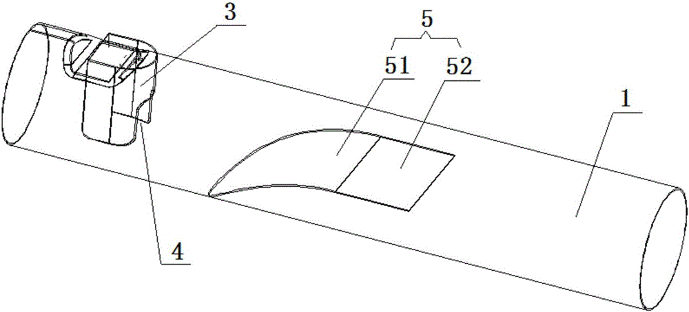
[0025] refer to Figure 1-4 , a new type of urea mixer of the present invention, including a mixing tube 1 for collecting urea and exhaust gas and a urea nozzle 2 vertically inserted at one end of the mixing tube 1, and a second urea nozzle surrounding the urea nozzle 2 is arranged in the mixing tube 1 A baffle 3, when the exhaust gas passes through the first baffle 3, the exhaust gas flow rate near the urea nozzle 2 can be increased, and the urea injected from the urea nozzle 2 will be blown away from the urea nozzle 2 at the fastest speed, reducing the amount of gas near the urea nozzle 2. At the same time, the first baffle 3 can disturb the exhaust gas flow, which enhances the mixing of the exhaust gas and urea; a gap 4 is provided on the side of the first baffle 3 opposite to the spraying direction of the urea nozzle 2, for urea The ure...


PUM


Abstract

The invention discloses a novel urea mixer. The novel urea mixer comprises a mixing pipe used for gathering urea and tail gas and a urea spraying nozzle vertically connected with one end of the mixing pipe in an inserted mode. A first baffle surrounding the urea spraying nozzle is arranged in the mixing pipe. A notch is formed in the lateral surface, opposite to the spraying direction of the urea spraying nozzle, of the first baffle. A second baffle opposite to the spraying direction of the urea spraying nozzle is further arranged in the portion, on one side of the first baffle, of the mixing pipe and is an arc baffle which extends upwards from the bottom of a turning surface of the mixing pipe, inclines in the direction away from the first baffle and then is gently bent in the tail gas flowing direction. The edges of two sides of the second baffle are in butt joint with the turning surface of the mixing pipe. An airflow passage for tail gas circulation is formed above the second baffle. The novel urea mixer is simple in structure, the problem of urea crystallization near the spraying nozzle and inside the mixer is solved, and the production cost is lowered.

Description

technical field [0001] The invention relates to the field of power machinery, more specifically, it relates to a novel urea mixer. Background technique [0002] The SCR injection system is used in the aftertreatment system of the diesel engine to eliminate the exhaust pollutant NO X system. The parts included in the SCR injection system are: Tianlan tank, air filter, metering injection pump, antifreeze solenoid valve, DCU components, nozzles and connecting pipelines. The system is controlled by the DCU. The metering injection pump will pass through the air filter. The clean compressed air, the antifreeze liquid passed through the antifreeze solenoid valve and the preheated blue liquid are mixed, sprayed into the mixer through the nozzle according to actual needs, and mixed with NO X A reduction reaction occurs to generate ammonia and water. The role of the mixer in the whole system is very important, which determines the mixing effect of urea and exhaust gas, thus affecti...

Claims


Application Information

Patent Timeline
IPC IPC(8): F01N3/28F01N3/20
CPCF01N3/2066F01N3/28F01N2570/14F01N2610/02F01N2610/08F01N2610/1453
Inventor 肖枫陶泽民杨树宝
Owner GUANGXI YUCHAI MASCH CO LTD
Why Eureka
Try Eureka