Air conditioner

a technology for air conditioners and compressors, applied in the field of air conditioners, can solve the problems of degrading the heat exchange efficiency of outdoor heat exchangers, and achieve the effects of prolonging reducing the time required for defrosting operation, and reducing the rotational speed of compressors

Active Publication Date: 2016-06-23
FUJITSU GENERAL LTD
View PDF11 Cites 14 Cited by
  • Summary
  • Abstract
  • Description
  • Claims
  • Application Information

AI Technical Summary

Benefits of technology

[0015]According to the air conditioner of the present invention that is configured as described above, the defrosting operation interval time is the time that corresponds to the capacity ratio, the indoor unit capacity, or the refrigerant pipe length. Accordingly, in the case where the rotational speed of the compressor during the defrosting operation cannot be increased due to an installation state of the air conditioner, the defrosting operation interval time is shortened in comparison with a case where the rotational speed of the compressor can be increased. Thus, the defrosting operation can be performed when the amount of the frost formed on the outdoor heat exchanger is still small. Therefore, such a situation where the time required for the defrosting operation is extended and the restoration of the heating operation is delayed can be prevented.

Problems solved by technology

When the outdoor heat exchanger is frosted, ventilation to the outdoor heat exchanger is inhibited by the frost, and thus heat exchange efficiency in the outdoor heat exchanger may be degraded.

Method used


Image

  • Air conditioner
  • Air conditioner
  • Air conditioner

Examples


example 1

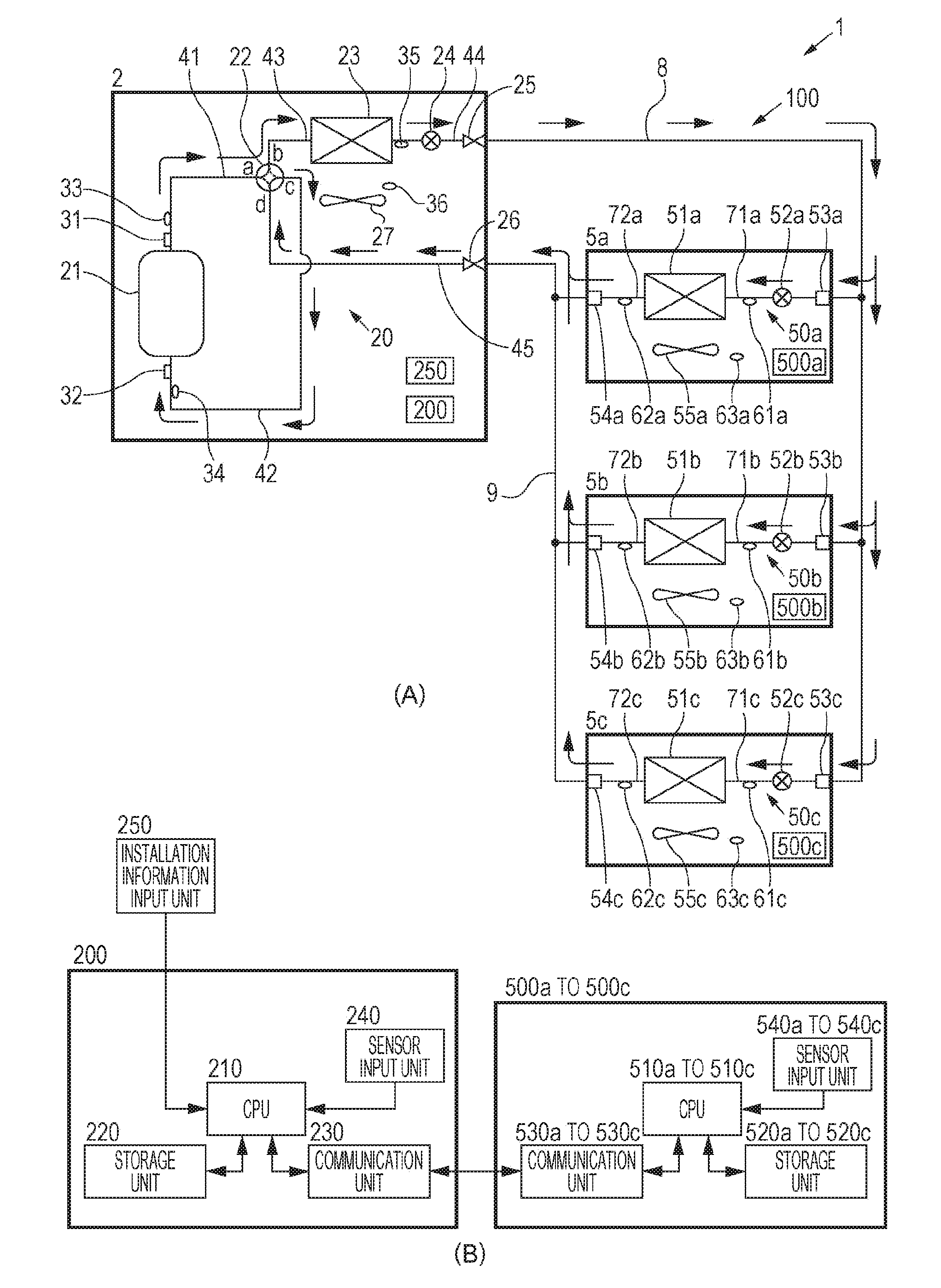
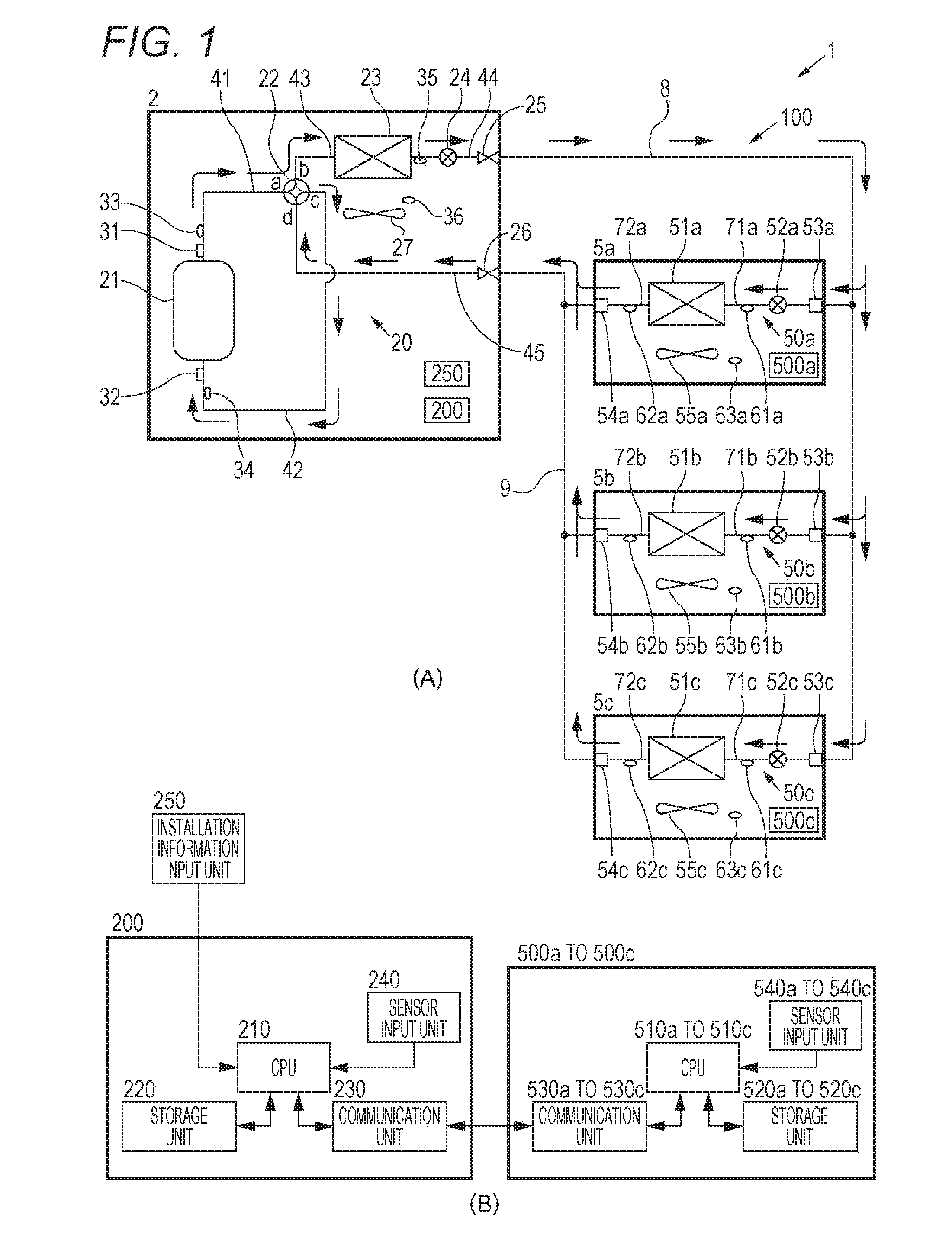
[0022]As depicted in FIG. 1(A), an air conditioner 1 of this example includes: one outdoor unit 2 that is installed on the outside of a building or the like; and three indoor units 5a to 5c that are coupled in parallel to the outdoor unit 2 via a liquid pipe 8 and a gas pipe 9. In detail, one end of the liquid pipe 8 is coupled to a closing valve 25 of the outdoor unit 2, and the other end thereof is branched and respectively coupled to liquid pipe coupling portions 53a to 53c of the indoor units 5a to 5c. In addition, one end of the gas pipe 9 is coupled to a closing valve 26 of the outdoor unit 2, and the other end thereof is branched and respectively coupled to gas pipe coupling portions 54a to 54c of the indoor units 5a to 5c. Thus, a refrigerant circuit 100 of the air conditioner 1 is configured.

[0023]First, the outdoor unit 2 will be described. The outdoor unit 2 includes a compressor 21, a four-way valve 22 as a flow passage switching unit, an outdoor heat exchanger 23, an ou...

example 2

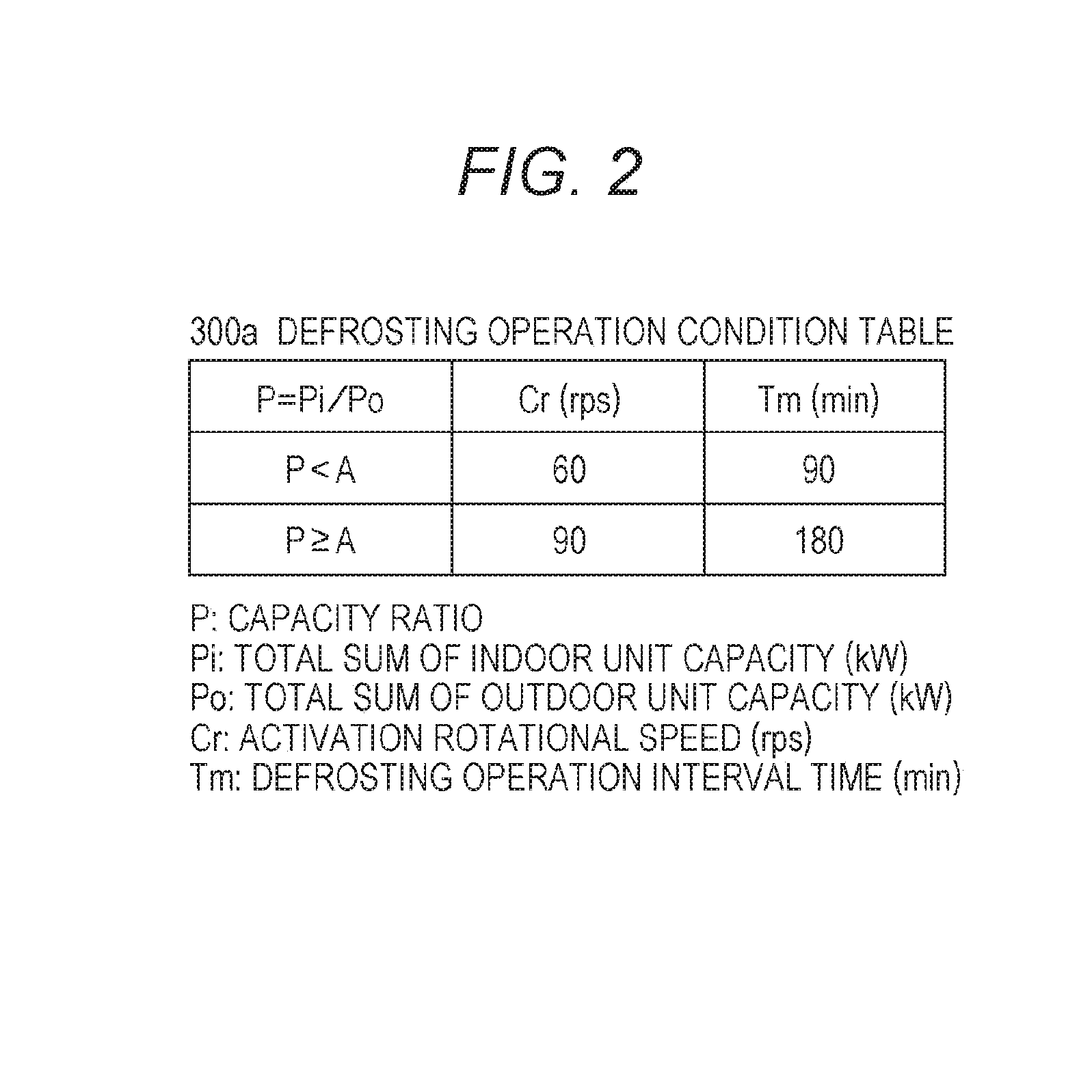
[0086]Next, a description will be made on a second embodiment of the air conditioner of the present invention by using FIG. 4. It should be noted that, since the configuration and the operation performance of the air conditioner and changing of the activation rotational speed of the compressor and the defrosting operation interval in the defrosting operation in accordance with the installation condition are the same as those in the first embodiment, the detailed description thereon will not be made in this embodiment. What differs from the first embodiment is that the activation rotational speed of the compressor and the defrosting operation interval are defined only in accordance with the total sum Pi of the indoor unit capacity in a defrosting operation condition table.

[0087]Similar to the defrosting operation condition table 300a depicted in FIG. 2, a defrosting operation condition table 300b that is depicted in FIG. 4 is stored in advance in the storage unit 220 of the outdoor u...

example 3

[0099]Next, a description will be made on a third embodiment of the air conditioner of the present invention by using FIG. 5. It should be noted that, since the configuration and the operation performance of the air conditioner and changing of the activation rotational speed of the compressor and the defrosting operation interval in the defrosting operation in accordance with the installation condition are the same as those in the first embodiment, the detailed description thereon will not be made in this embodiment. What differs from the first embodiment is that the activation rotational speed of the compressor and the defrosting operation interval are defined in consideration of a length of the refrigerant pipe for coupling the outdoor unit and the indoor units in addition to the capacity ratio in a defrosting operation condition table.

[0100]Similar to the defrosting operation condition table 300a depicted in FIG. 2, a defrosting operation condition table 300c that is depicted in ...


PUM


Abstract

An outdoor unit control unit 200 has a defrosting operation condition table 300a that defines a defrosting operation interval time Tm in accordance with a total sum of rated capacity of indoor units 5a to 5c and a refrigerant pipe length as lengths of a liquid pipe 8 and a gas pipe 9. The outdoor unit control unit 200 uses the total sum of the rated capacity of indoor units 5a to 5c input by using an installation information input unit 250 and refers to the defrosting operation condition table 300a, so as to determine the defrosting operation interval time Tm. Then, the outdoor unit control unit 200 forcibly performs a defrosting operation when the defrosting operation interval time Tm elapses without establishment of a defrosting operation start condition since the last defrosting operation is terminated.

Description

TECHNICAL FIELD[0001]The present invention relates to an air conditioner in which at least one outdoor unit and at least one indoor unit are mutually coupled by plural refrigerant pipes.BACKGROUND ART[0002]An air conditioner in which at least one outdoor unit and at least one indoor unit are mutually coupled by plural refrigerant pipes has been suggested. In the case where a temperature of an outdoor heat exchanger becomes equal to or less than 0° C. when this air conditioner performs a heating operation, the outdoor heat exchanger may be frosted. When the outdoor heat exchanger is frosted, ventilation to the outdoor heat exchanger is inhibited by the frost, and thus heat exchange efficiency in the outdoor heat exchanger may be degraded. Thus, when frosting occurs to the outdoor heat exchanger, a defrosting operation has to be performed to defrost the outdoor heat exchanger.[0003]For example, in an air conditioner described in Patent Literature 1, an outdoor unit that includes a com...

Claims


Application Information

Patent Timeline
Patent Type & Authority Applications(United States)
IPC IPC(8): F25B47/02F25B25/00F25B41/04
CPCF25B47/025F25B2347/023F25B25/005F25B41/046F25B2347/02F25B13/00F25B2313/006F25B2313/0233F25B2313/02741F25B2313/0314F25B2313/0315F25B2600/025F25B2700/1931F25B2700/1933F25B2700/2106F25B2700/21151F25B2700/21152F24F11/30F24F11/42F24F11/52
Inventor KIMURA, TAKASHIHAYASHI, KUNIKO
Owner FUJITSU GENERAL LTD
Why Eureka
Try Eureka