
Computer system for virtualizing I/O device and method of operating the same and hub device

Active Publication Date: 2016-06-23
AKIB SYST
View PDF25 Cites 3 Cited by
  • Summary
  • Abstract
  • Description
  • Claims
  • Application Information

AI Technical Summary

Benefits of technology

The present invention provides a way to connect two computers and establish information on the input output devices (I / O devices) of the other computer. This allows for virtualization of the I / O devices between the two computers. The technical effect is improved connectivity and flexibility in accessing information from different computers.

Problems solved by technology

However, enhancing the efficiency of utilization on the server side (CPU side) results in burden on an I / O (input / output device) side being disadvantageously increased to cause further complication.
In this case, in tell is of security, an individual physical I / O is often provided, and this causes an increase in the number of I / Os.
Consequently, however, it is also necessary to provide an EtherNet (registered trademark) and a fiber channel and the like according to the request of the user, and further necessary to increase the number of various physical I / Os, with the result that the system is likely to be complicated.
For example, the efficiency of utilization of the server is enhanced by the virtualization of the server, and thus a band consumed by the I / O is increased, with the result that the bandwidth of an I / O bus may be a bottleneck in today's computer systems.
However, the efficiency of storage and USBs and the like are only partially enhanced with these methods, with the result that it may be difficult to solve the problem of the entire I / O.

Method used


Image

  • Computer system for virtualizing I/O device and method of operating the same and hub device
  • Computer system for virtualizing I/O device and method of operating the same and hub device
  • Computer system for virtualizing I/O device and method of operating the same and hub device

Examples


Embodiment Construction

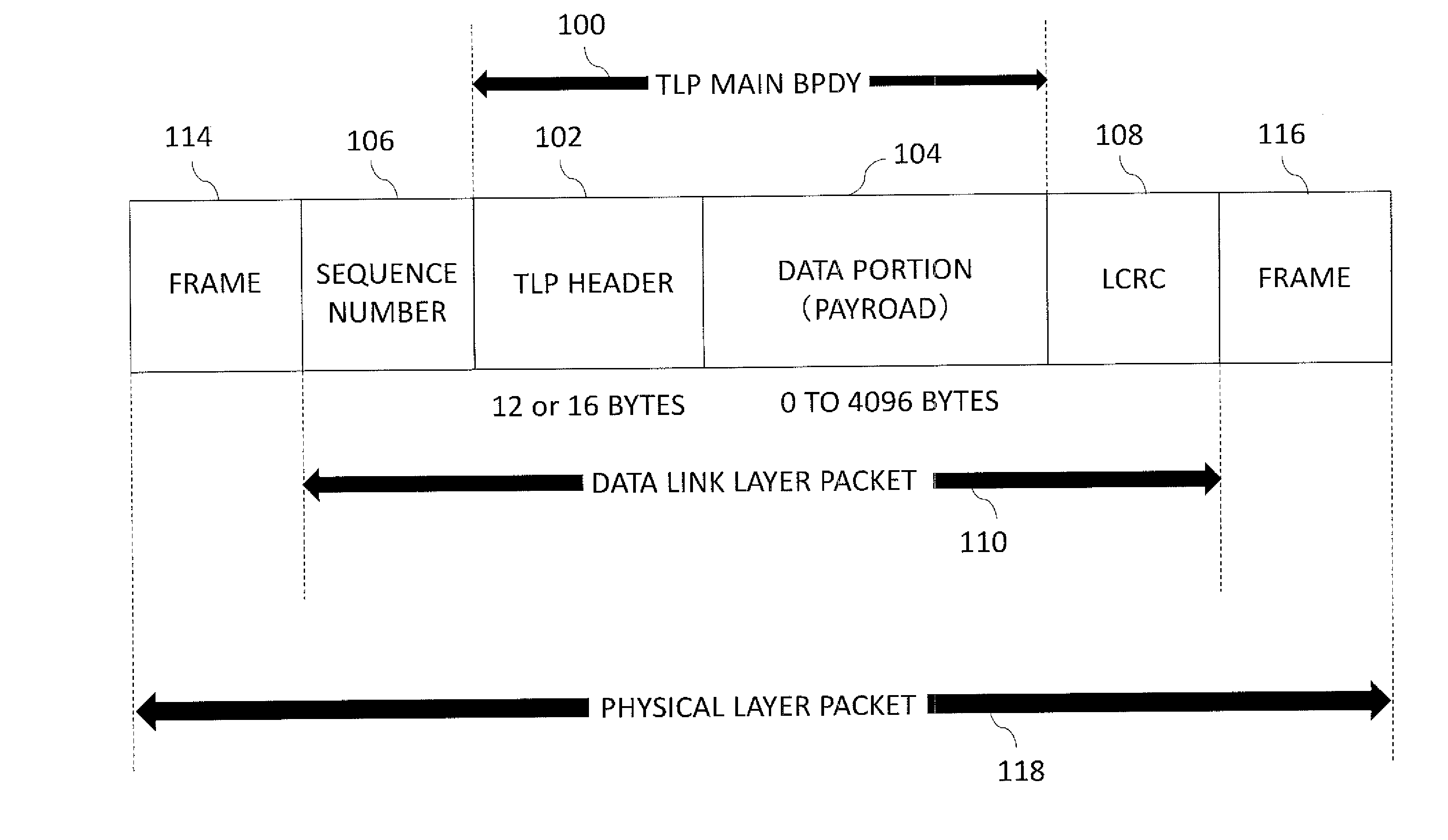
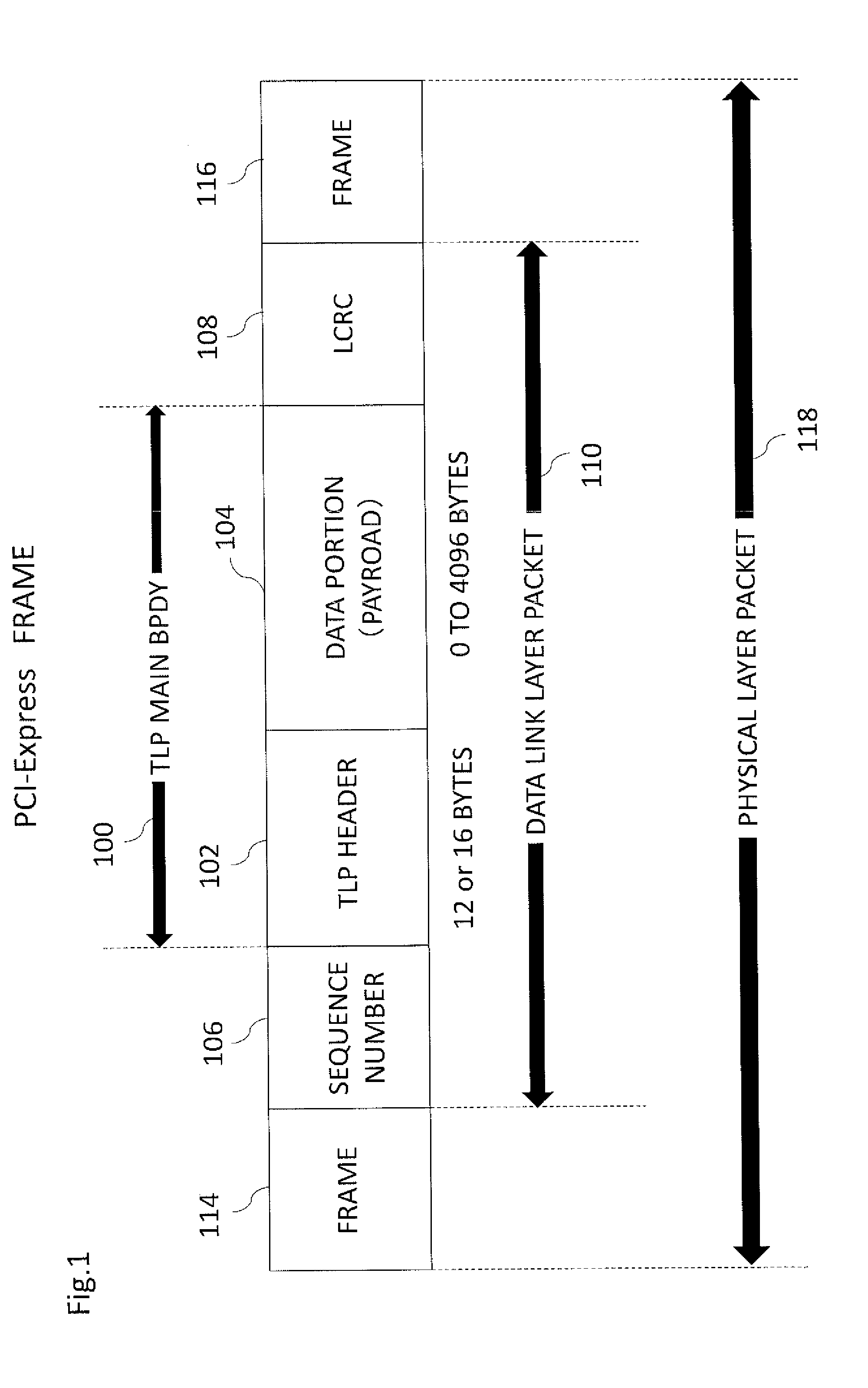
[0045]FIG. 1 is an illustrative diagram showing an outline of the format of a TLP;

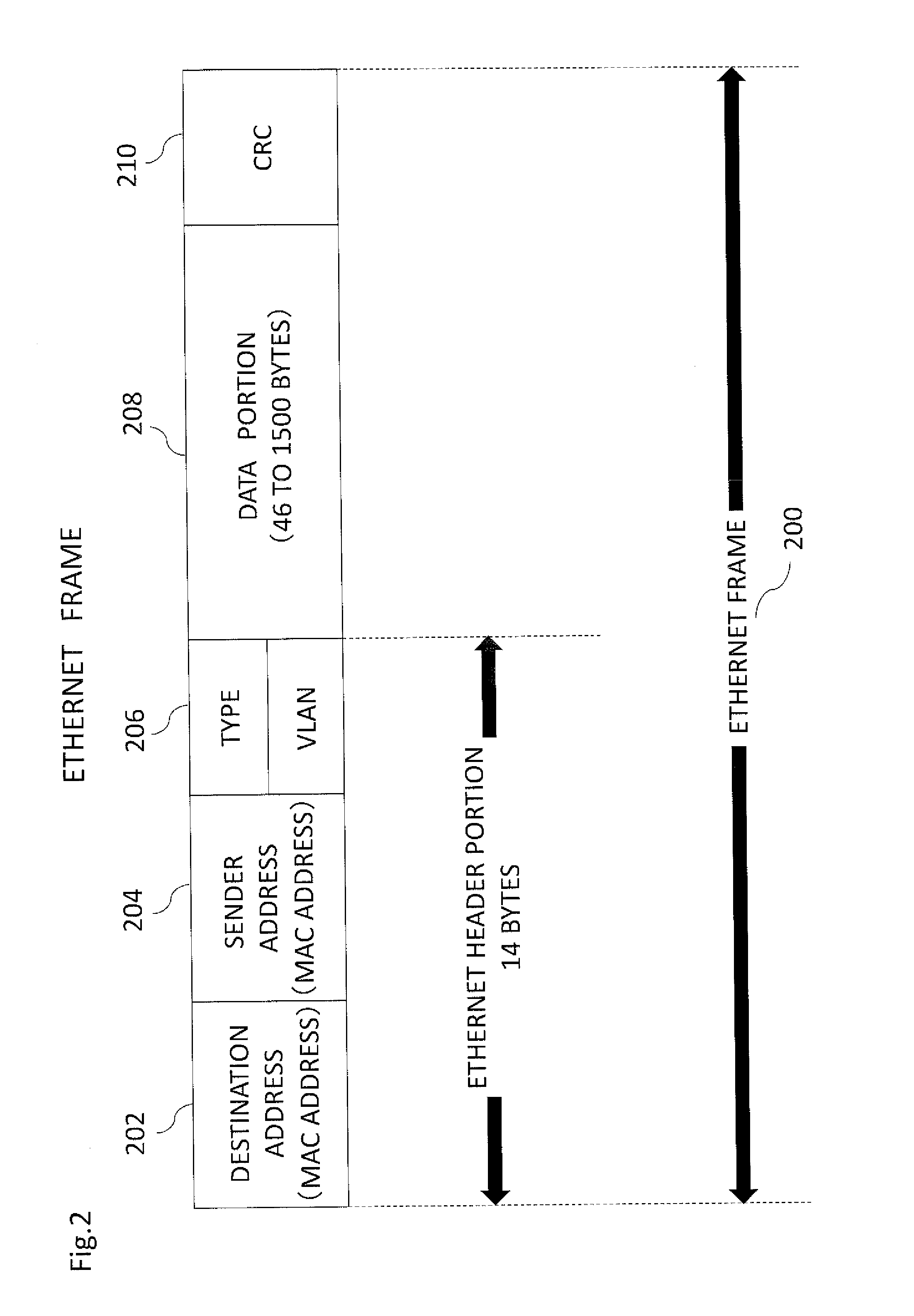
[0046]FIG. 2 is an illustrative diagram showing an outline of an Ethernet frame;

[0047]FIG. 3 is a block diagram of the configuration of a HUB device;

[0048]FIG. 4 is an illustrative diagram showing an example of a general configuration using a PCI-Express;

[0049]FIG. 5 is a diagram of a configuration when a computer using the PCI-Express is connected;

[0050]FIG. 6 is a block diagram of the configuration of a dedicated NIC device; and

[0051]FIG. 7 is a flowchart showing the flow of startup of a system when the virtualization of an I / O is performed.

DESCRIPTION OF EMBODIMENTS

[0052]A preferred embodiment of the present invention will be described below with reference to the drawings.

[0053]In the present embodiment, a description will be given of the fact that in a system which forms a network by the utilization of the internal slot interface of a PC, it is possible to easily realize the virtualization of an I / ...


PUM


Abstract

Provided are a system and related devices whereby it is easy to achieve I / O virtualization. A HUB device according to the present invention is provided with a switch for internal slots in a PC (for example, internal PCI-Express slots) and is configured to be able to interconnect internal slots in other PCs. In a computer system in which one or more PCs are interconnected by this HUB device, which serves as the central point of connection, each PC can “see” I / O devices of other PCs through the switch for the internal slots. Therefore, each PC creates a device list including I / O devices of the PC and I / O devices of other PCs, and the OS of the PC uses the device list. As a result, it is possible to easily achieve I / O virtualization.

Description

TECHNICAL FIELD[0001]The present invention relates to a technology for virtualizing an I / O device (input / output device) of a computer.BACKGROUND ART[0002]Today, in widely used server systems, virtualization is widely performed. In other words, so-called virtualization of the server is performed. By virtualizing the server, it is possible to enhance the efficiency of utilization of physical resources on the server side.[0003]However, enhancing the efficiency of utilization on the server side (CPU side) results in burden on an I / O (input / output device) side being disadvantageously increased to cause further complication.[0004]For example, due to a request from a user, it may be necessary to connect an arbitrary virtual server to an arbitrary network. In this case, in tell is of security, an individual physical I / O is often provided, and this causes an increase in the number of I / Os.[0005]For example, it is necessary to perform the sharing of storage in order to store a virtual server....

Claims


Application Information

Patent Timeline
IPC IPC(8): G06F13/42G06F13/40G06F9/44G06F9/455
CPCG06F13/4282G06F9/45558G06F2009/45579G06F9/441G06F13/4022G06F13/385
Inventor NAKAYAMA, HIDETOIWASAWA, KENTARO
Owner AKIB SYST
Learn More