Automatic observation apparatus for detecting mineral samples

a technology of automatic observation and mineral samples, applied in the field of experimental detection, can solve the problems of inability to quantify the rotation of samples, low efficiency, complex operation, etc., and achieve the effects of convenient and efficient fixation, improved accuracy of mineral sample detection, and avoiding stray light interferen

Inactive Publication Date: 2016-06-30
CHINA UNIV OF PETROLEUM (EAST CHINA)
View PDF6 Cites 9 Cited by
  • Summary
  • Abstract
  • Description
  • Claims
  • Application Information

AI Technical Summary

Benefits of technology

[0004]To overcome deficiencies, such as low efficiency, large error, incapability of quantitatively and accurately observing optical characteristics of minerals, harmful to physical health of those who are identifying samples, and incapability of fixing the samples firmly by hands and avoiding stray light interference, of holding mineral samples by hands and observing directly from the eyepiece window in the prior art, the present invention provides an automatic observation apparatus for detecting mineral samples, where samples are fixed by mechanical apparatuses so that the samples are fixed conveniently and efficiently; furthermore, the samples are accurately positioned and rotated by controlling a stepper motor by a computer, and an image observed in the eyepiece is transmitted onto a computer screen by a camera and may be saved in a specified file. In this way, the working efficiency of detecting mineral samples and the accuracy of identification are both improved, and the requirements on the proficiency and experience of the mineral detectors are reduced.
[0007]Compared with the prior art, the present invention has the following beneficial effects: fixing mineral samples by mechanical apparatuses, the mineral samples are fixed conveniently and efficiently; sealing the observation environment by the mechanical apparatuses, the stray light interference is avoided; quantitatively rotating the samples by electromechanical control equipment, the mineral samples are observed at different angles of rotation; transmitting test results of mineral samples to be detected in digital signals, the accuracy of detection of mineral samples is improved.

Problems solved by technology

Such ways not only are complex in operation and low in efficiency and highly depend upon the proficiency and experience of the observers, but also fail to realize quantified rotation of samples.
A too narrow eyepiece window also brings great inconvenience to the observation and identification, and the observed image can not be saved.
Meanwhile, due to the unsealed sample observation environment, it is unable to avoid the stray light interference from the external environment during the rotation of samples by fingers, and also difficult to ensure close and stable contact between undetermined mineral samples to be detected and the optical surface so that the observers can not observe the accurate optical characteristics of the mineral samples to be detected from the optical instruments.
Consequently, there are large errors in the obtained identification results of the minerals.
When small mineral samples are fixed and rotated by hands, the fingers are likely to touch the virulent refracting oil so that the physical health of those who are identifying the samples is threatened; and the environment is polluted.
This utility model highly depends upon the proficiency and experience of the detectors, fails to realize reliable fixation of the optical instrument and also accurate and automatic quantified rotation of samples, fails to avoid stray light interference in the contact surfaces and the eyepiece, and also fails to save the observed results.

Method used


Image

  • Automatic observation apparatus for detecting mineral samples
  • Automatic observation apparatus for detecting mineral samples
  • Automatic observation apparatus for detecting mineral samples

Examples


Embodiment Construction

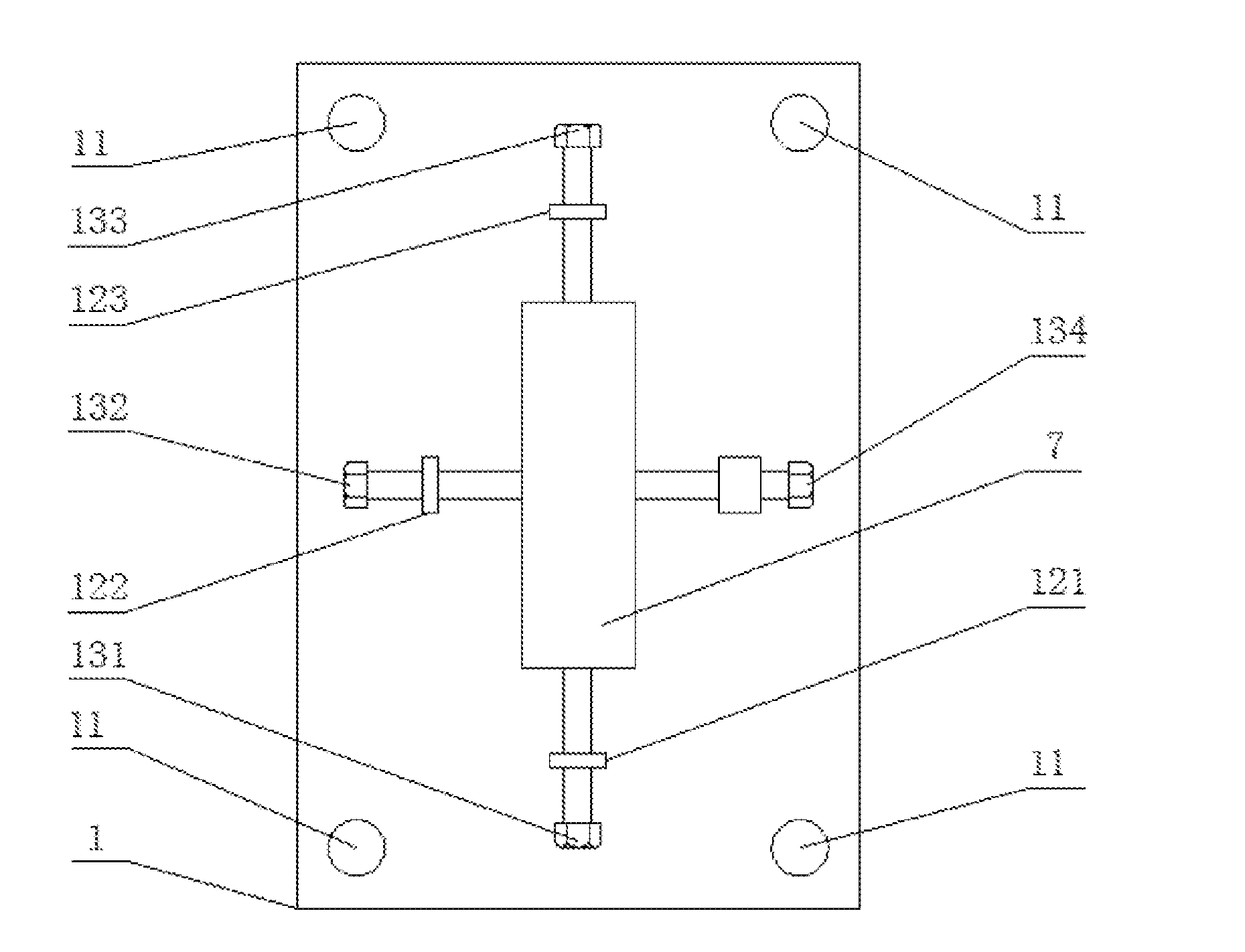
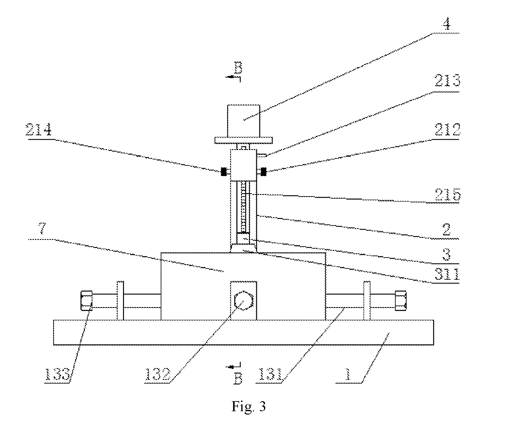
[0012]As shown in FIG. 1, an automatic observation apparatus for detecting mineral samples includes a base 1, a supporting arm 2, a sample fixing device 3, a stepper motor 4, a high-definition camera 5 and a control system 6.

[0013]The base 1 is a rectangular metal plate, a through hole 11 is respectively formed at four corners of the base 1, and the base 1 is fixed on a desktop by passing four screws through the through holes 11; a first lug 121, a second lug 122 and a third lug 123 are provided on the base 1, and the supporting arm 2 is embedded in the base 1; the first lug 121 is arranged in opposite to the third lug 123, the second lug 122 is arranged in opposite to the supporting arm 2, and a connecting line of the first lug 121 and the third lug 123 is vertical to a connecting line of the second lug 122 and the supporting arm 2; a threaded through hole is formed on the first lug 121, and a first screw 131 is mounted in the threaded through hole; a threaded through hole is forme...


PUM

PropertyMeasurementUnit
shapeaaaaaaaaaa
softaaaaaaaaaa
angle of rotationaaaaaaaaaa

Abstract

An automatic observation apparatus for detecting mineral samples comprises a base (1), a supporting arm (2), a sample fixing device (3), a stepper motor (4), a high-definition camera (5) and a control system (6). A refractometer is fixed on the base (1). A vertical through hole is formed at the top end of the supporting arm (2), and a lifting rod (211) penetrates through the vertical through hole and is matched with the vertical through hole in shape. A cavity is formed at the top end of the supporting arm (2), a gear (216) is mounted in the cavity, and the gear (216) is meshed with a rack (215) of the lifting rod (211). The sample fixing device (3) is a right-hexagonal-prism shell with the top end sealed, a spring (312) is arranged in a vertical hole of the sample fixing device, a sample locating head fixing device (314) is arranged at the lower end of the spring (312), a blind hole is formed in the lower end of the sample locating head fixing device (314), and a sample locating head (316) is matched with the blind hole in the lower end of the sample locating head fixing device (314). The apparatus can conveniently and efficiently fix samples, stray light interference is avoided, mineral samples can be rotated to be observed from different angles, and mineral sample detection accuracy is improved.

Description

TECHNICAL FIELD[0001]The present invention belongs to the field of experimental detection, and particularly relates to an automatic observation apparatus for detecting mineral samples, which is used for realizing the fixation, automatic rotation and automatic observation of mineral samples.BACKGROUND OF THE INVENTION[0002]At present, the known ways of observing and identifying mineral samples by some optical instruments are almost all to place samples on an optical surface coated with refracting oil, fix and rotate the mineral samples by hands, and then observe directly from the eyepiece window by eyes to obtain readings at different angles of rotation of the samples. Such ways not only are complex in operation and low in efficiency and highly depend upon the proficiency and experience of the observers, but also fail to realize quantified rotation of samples. A too narrow eyepiece window also brings great inconvenience to the observation and identification, and the observed image ca...

Claims


Application Information

Patent Timeline
Patent Type & Authority Applications(United States)
IPC IPC(8): G01N21/41G01N21/87
CPCG01N21/4133G01N2201/025G01N21/87G01N33/38
Inventor SONG, YINGYANG, YONGQIANGQIU, LONGWEIZHAO, YUMINGYANG, WEICHAOQI, YINGSTEPASHKO, ANDREI
Owner CHINA UNIV OF PETROLEUM (EAST CHINA)
Why Eureka
Try Eureka