

Organic light emitting display device
Active Publication Date: 2016-06-30
LG DISPLAY CO LTD
View PDF2 Cites 22 Cited by
- Summary
- Abstract
- Description
- Claims
- Application Information
AI Technical Summary
Benefits of technology
[0012]The inventors of the present disclosure have continued various studies for improving a decrease in image luminance uniformity which worsens as a top-emission organic light emitting display device is increased in size. To be specific, the inventors have continued on research and development of a disposition structure of a cathode
Problems solved by technology
Therefore, when an anode line for supplying an anode voltage ELVDD and a cathode line for supplying a cathode voltage
Method used
View moreImage
Smart ImageViewing Examples

Examples
 PUM
 Abstract
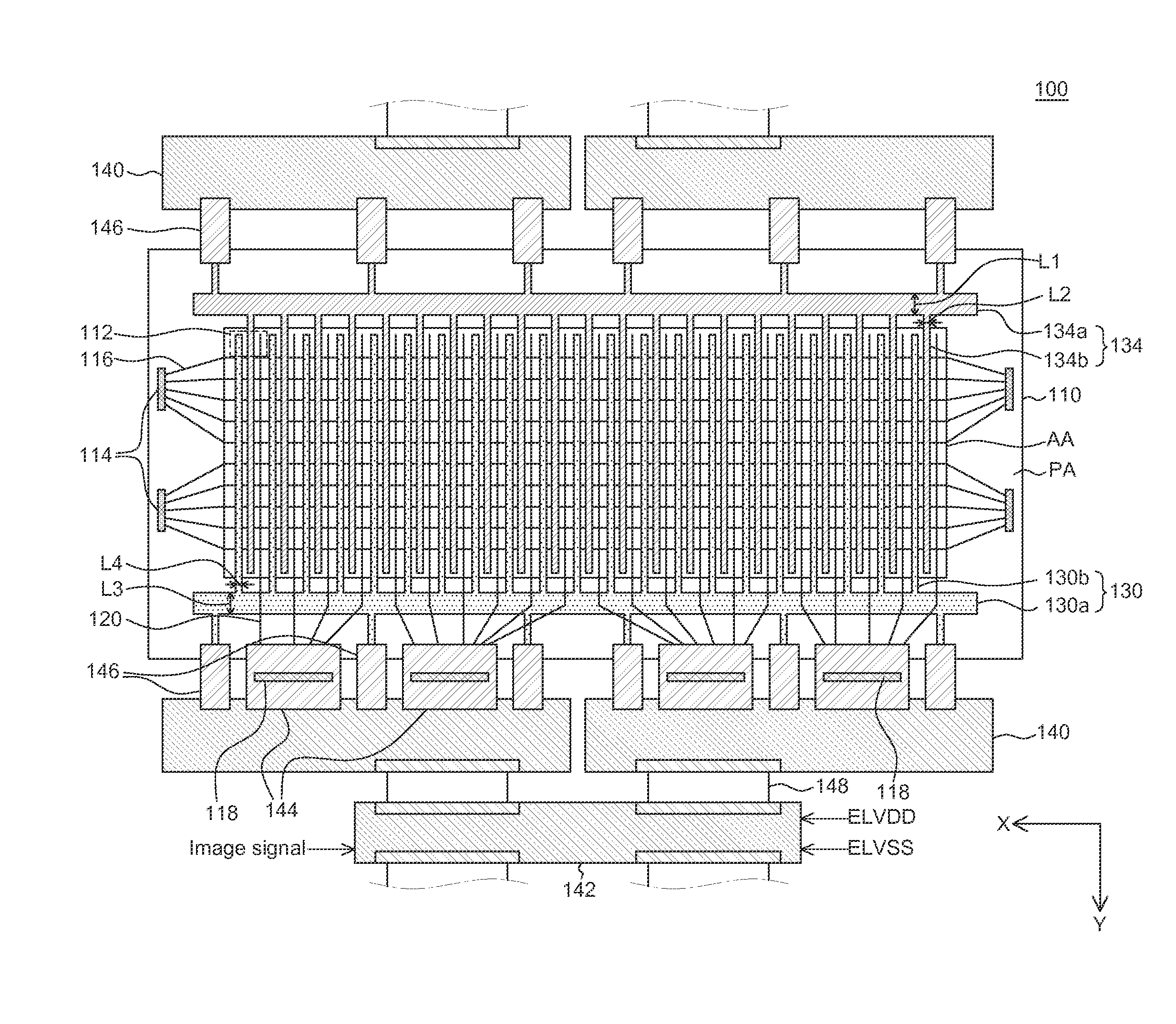
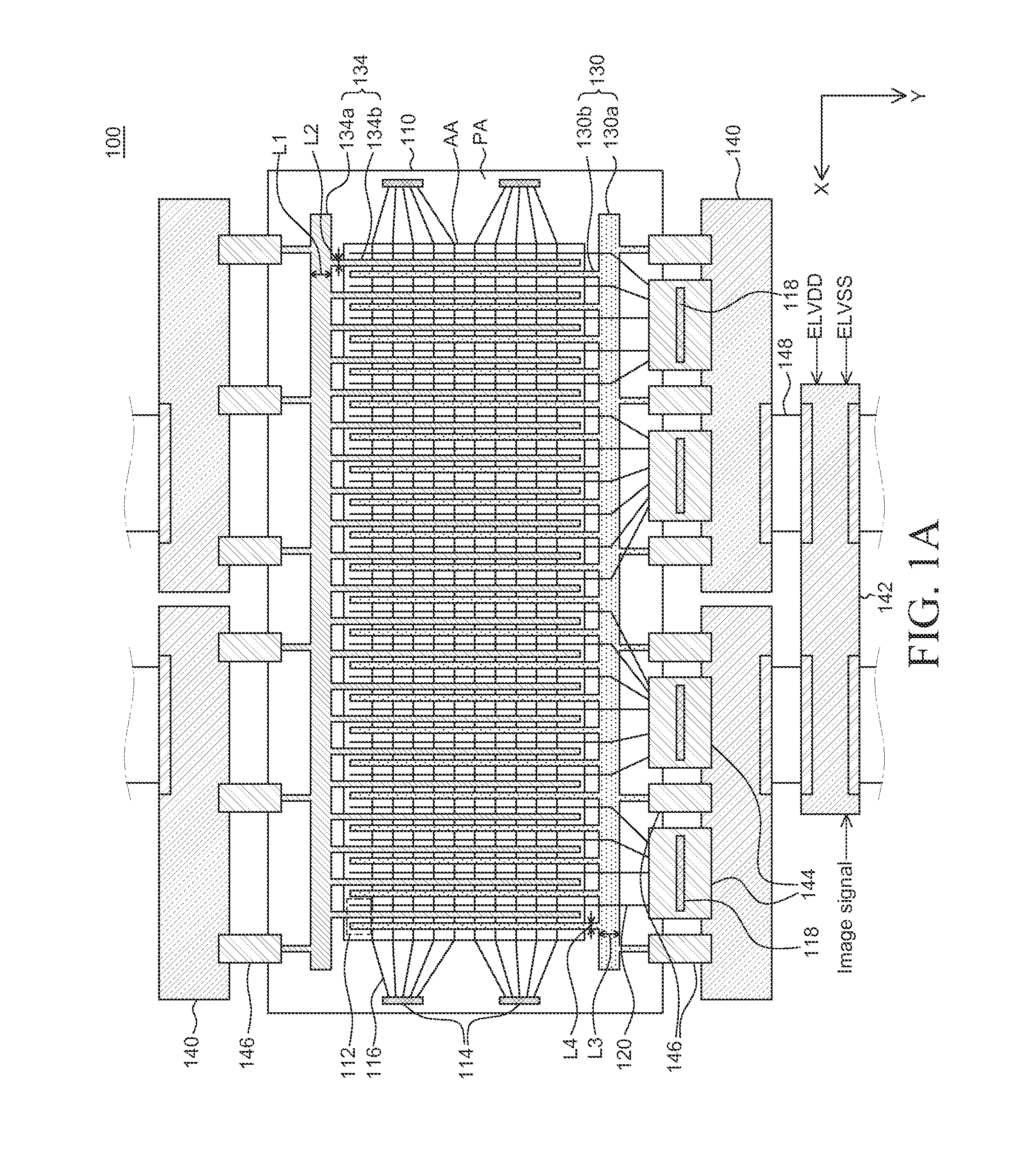
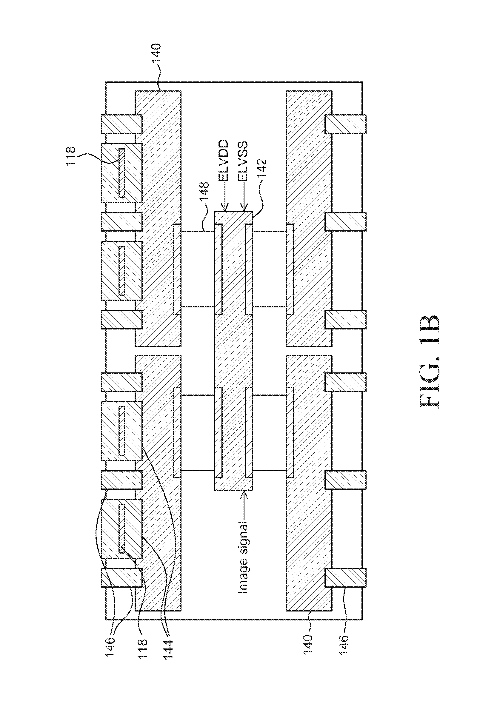
Provided is an organic light emitting display device. The organic light emitting display device includes: a plurality of sub-pixels including an anode and a cathode; an anode line configured to supply an anode voltage to the anode; and a cathode line configured to supply a cathode voltage to the cathode, and in each of the plurality of sub-pixels, a direction of an anode voltage input of the anode line and a direction of a cathode voltage input of the cathode line are different from each other and face each other in order to reduce a deviation in a potential difference between the anode and the cathode. Thus, it is possible to improve uniformity in the potential difference between the anode and the cathode caused by a line resistance.
Description
CROSS-REFERENCE TO RELATED APPLICATIONS[0001]This application claims the priority of Korean Patent Application No. 10-2014-0196003 filed on Dec. 31, 2014, and Korean Patent Application No. 10-2015-0061775 filed on Apr. 30, 2015 in the Korean Intellectual Property Office, which are all incorporated herein by reference.BACKGROUND OF THE INVENTION[0002]1. Field of the Invention[0003]The present disclosure relates to an organic light emitting display device, and more particularly, to an organic light emitting display device including a voltage supply line structure which can improve luminance uniformity of the organic light emitting display device by reducing a deviation in a potential difference between an anode and a cathode depending on a position of an active area of the organic light emitting display device when the organic light emitting display device is enlarged.[0004]2. Description of the Related Art[0005]As the age of information technology has proceeded, the field of display ...
Claims
Login to View More Application Information
Patent Timeline
 IPC IPC(8): H01L27/32
CPCH01L27/3218H01L27/3279G09G3/3233G09G2320/0223G09G2300/0426H10K59/1315H10K59/131H10K59/353
InventorPARK, JAEHEE
OwnerLG DISPLAY CO LTD