Light field image capturing apparatus including shifted microlens array

Active Publication Date: 2016-06-30
SAMSUNG ELECTRONICS CO LTD
View PDF16 Cites 26 Cited by
  • Summary
  • Abstract
  • Description
  • Claims
  • Application Information

AI Technical Summary

Benefits of technology

[0029]According to the present embodiment, a plurality of microlenses within the microlens array 120 are shifted with respect to pixels corresponding to the plurality of microlenses so that a plurality of overlapping images having different viewing points may be easily captured without using a complicated optical configuration. As a result, in a light fie

Problems solved by technology

However, in active methods, both an additional light source and an additional optical system for radiating light onto t

Method used


Image

  • Light field image capturing apparatus including shifted microlens array
  • Light field image capturing apparatus including shifted microlens array
  • Light field image capturing apparatus including shifted microlens array

Examples


Example

[0035]Reference will now be made in detail to embodiments, examples of which are illustrated in the accompanying drawings, wherein like reference numerals refer to like elements throughout. Sizes of elements in the drawings may be exaggerated for clarity and convenience of explanation. In this regard, the present embodiments may have different forms and should not be construed as being limited to the descriptions set forth herein. Accordingly, the embodiments are merely described below, by referring to the figures, to explain aspects of the present description.

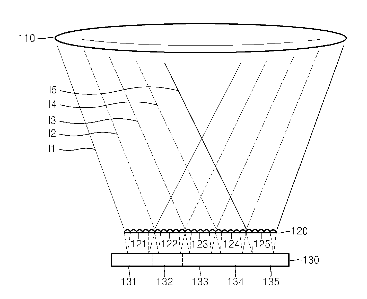
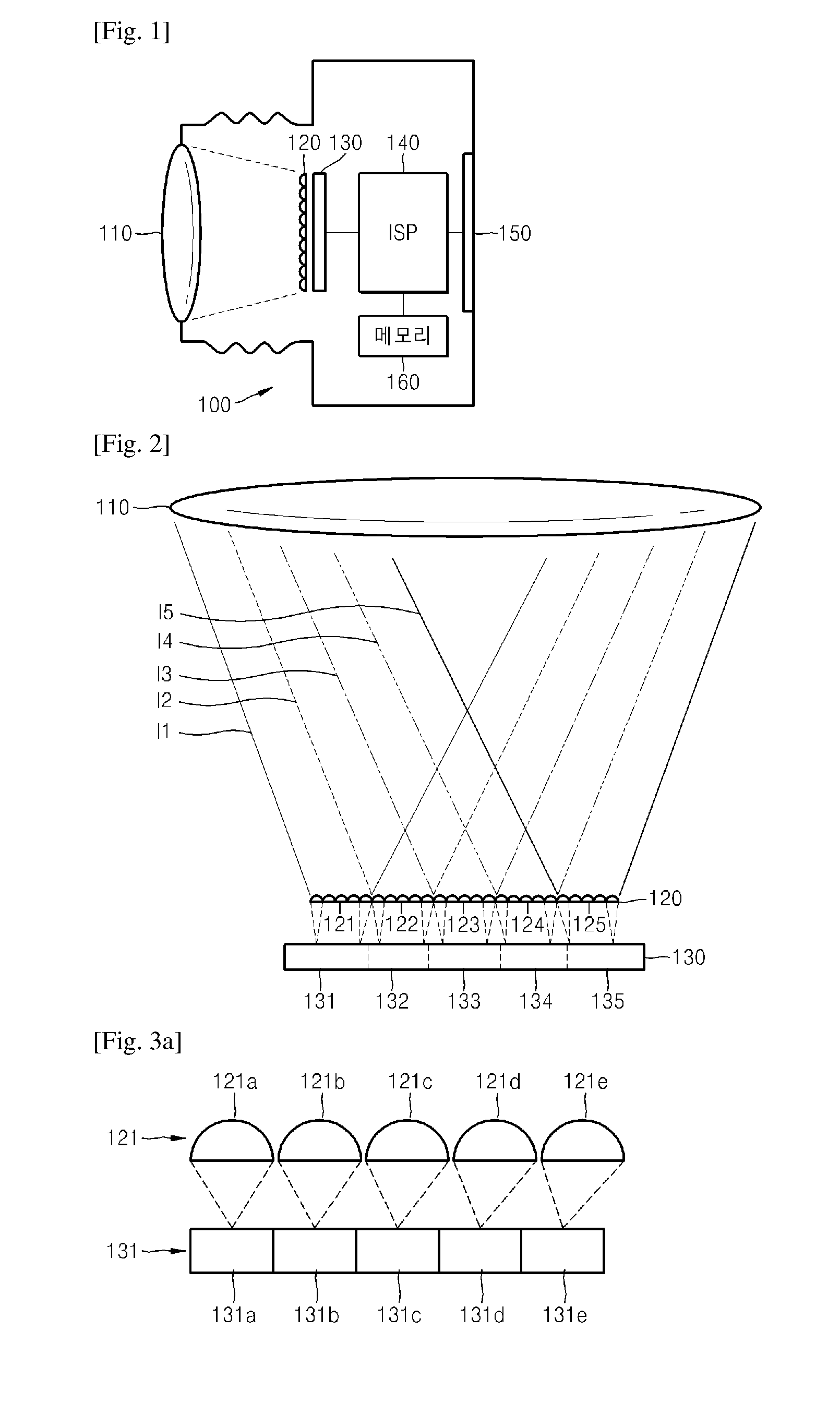
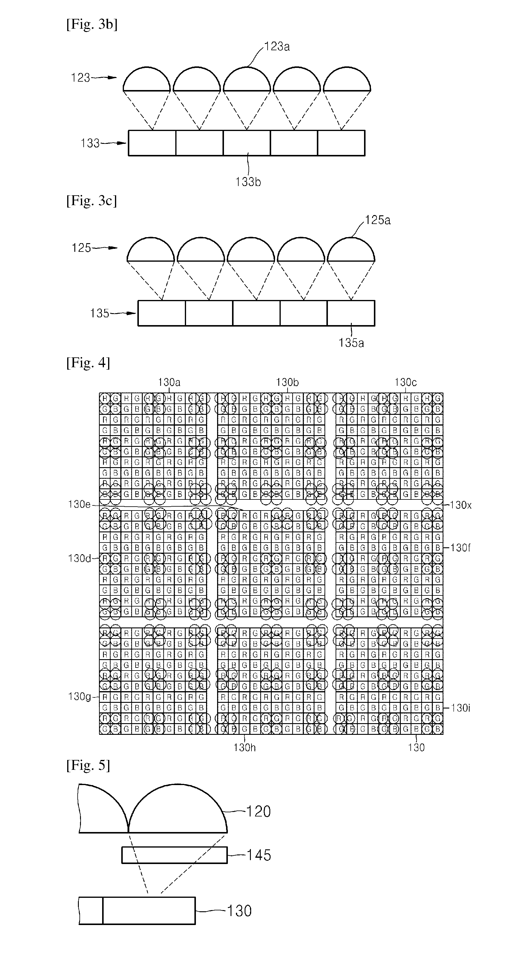
[0036]FIG. 1 schematically illustrates the overall configuration of a light field image capturing apparatus according to an example embodiment. Referring to FIG. 1, a light field image capturing apparatus 100 according to the current embodiment may include, for example, an objective lens 110 that focuses light incident from an external object (not shown), an image sensor 130 including a plurality of pixels, wherein the image s...


PUM


Abstract

A light field image capturing apparatus including a shifted microlens array, the light field image capturing apparatus including: an objective lens focusing light incident from an external object; an image sensor including a plurality of pixels, the image sensor outputting an image signal by detecting incident light; and a microlens array disposed between the objective lens and the image sensor and including a plurality of microlenses arranged in a two-dimensional manner, the plurality of microlenses corresponding to the plurality of pixels, wherein at least a part of the plurality of microlenses is shifted in a direction with respect to the pixels corresponding to the at least a part of the plurality of microlenses.

Description

TECHNICAL FIELD[0001]One or more embodiments of the present disclosure relate to light field image capturing apparatuses, and more particularly, to light field image capturing apparatuses including shifted microlens arrays.BACKGROUND ART[0002]As three-dimensional (3D) display apparatuses that may display depth images have been developed and their demands are increasing, 3D contents become significant. Thus, there is significant research directed towards a variety of 3D image capturing apparatuses in which a user himself / herself may manufacture 3D contents.[0003]Methods of obtaining information regarding a distance from a 3D image capturing apparatus to an object may largely include active methods and passive methods. As a part of active methods, there are two representative methods, such as a time-of-flight (TOF) technique, whereby light is radiated onto the object and is reflected from an object and the light is detected so that a time for light movement may be determined, and tria...

Claims


Application Information

Patent Timeline
IPC IPC(8): H04N5/225G02B3/00H04N13/02H04N13/232
CPCH04N5/2254H04N2213/001G02B3/0056H04N13/0203G03B35/08G02B27/0075H04N13/232H04N13/204H04N23/957H04N23/55
Inventor SHIN, JUNGSOONLEE, SEUNGKYU
Owner SAMSUNG ELECTRONICS CO LTD
Why Eureka
Try Eureka