Radiation capturing system

Active Publication Date: 2017-10-05
KONICA MINOLTA INC
View PDF24 Cites 4 Cited by
  • Summary
  • Abstract
  • Description
  • Claims
  • Application Information

AI Technical Summary

Benefits of technology

[0008]The present invention is conceived in view of the above, and the object of the present invention is to provide a radiation capturing system using a Talbot

Problems solved by technology

Therefore, even if only an absorptive image is necessary for purposes such as confirming positioning of the subject before actual capturing by fringe scanning, adjustment and status monitoring of the grating, radiation source, radiation detector, etc., and collection of calibration data for devices such as the

Method used


Image

  • Radiation capturing system
  • Radiation capturing system
  • Radiation capturing system

Examples


Example

First Embodiment

(Configuration of Radiation Capturing System)

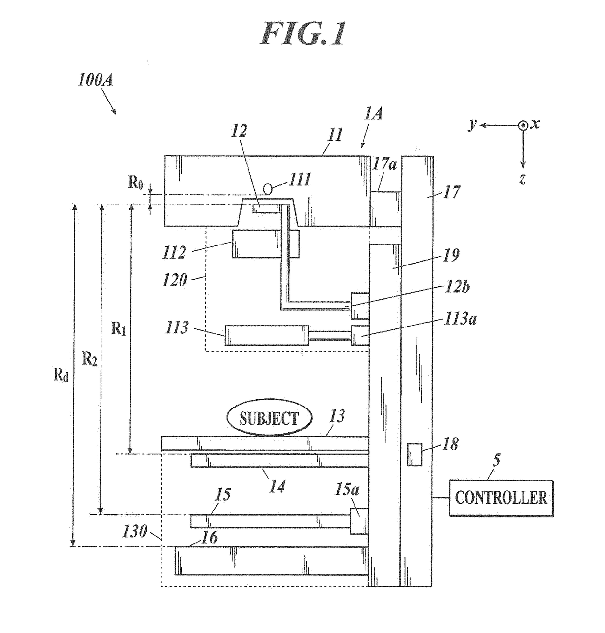
[0055]FIG. 1 is a diagram schematically showing a radiation capturing system 100A according to a first embodiment of the present invention.

[0056]As shown in FIG. 1, the radiation capturing system 100A includes a radiation capturing apparatus 1A and a controller 5. The radiation capturing apparatus 1A performs X-ray capturing with a Talbot-Lau interferometer and the controller 5 generates a reconstructed image using the moire fringe images obtained in the X-ray capturing. According to the description below, the radiation capturing system performs capturing using the X-ray, but other radiation such as a neutron ray, a gamma ray, etc. can be used.

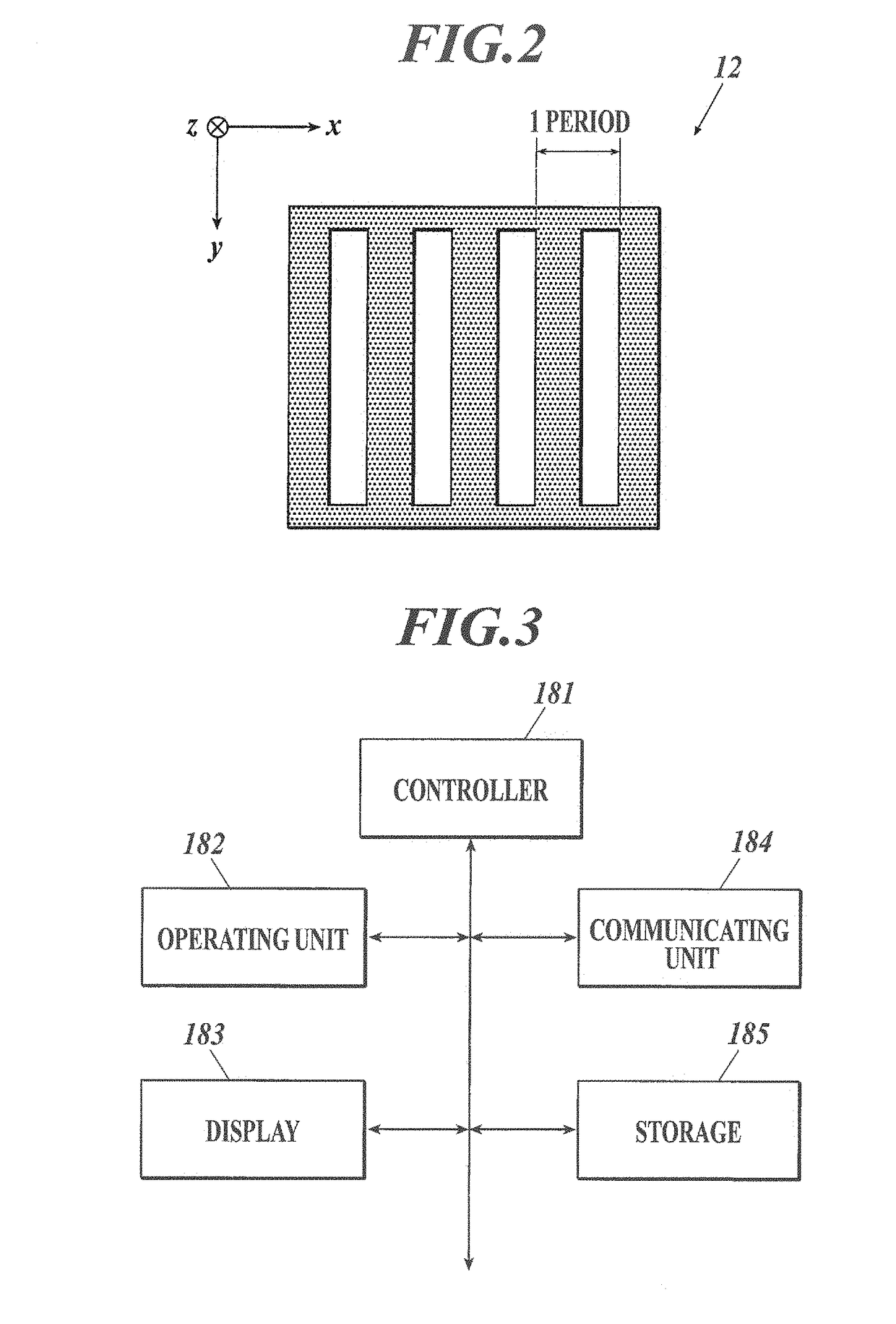
[0057]As shown in FIG. 1, the radiation capturing apparatus 1A includes a radiation source 11, a first cover unit 120 including a multi-slit 12, a second cover unit 130 including a subject stage 13, a first grating 14, a second grating 15, and a radiation detector 16, a post 17, a ma...

Example

Second Embodiment

[0142]The second embodiment of the present invention is described below.

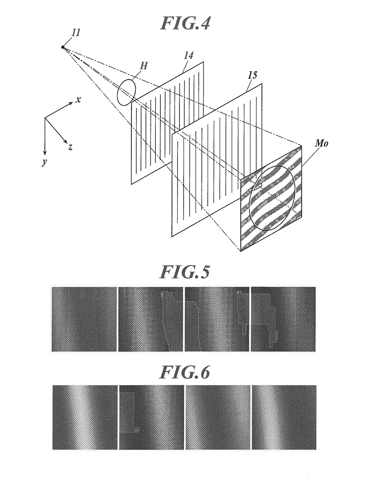
[0143]According to the second embodiment, the moire fringe image with the reduced visibility of the moire fringe is obtained by capturing in a state in which one or more gratings among the three gratings which are the multi-slit 12, the first grating 14, and the second grating 15 is rotated around the radiation irradiating axis with respect to the grating position in the capturing by the fringe scanning state. The influence provided to the moire fringe is different depending on the rotated grating. First, the phenomenon which occurs by rotating each grating is described. Here, the phase of the moire fringe is determined by the relative angle of the three gratings. When the two gratings are rotated in the same direction in the same angle, it is the same effect as rotating the grating which is not rotated in the opposite direction in the same angle.

[0144]The grating position suitable for capturing...

Example

Third Embodiment

[0178]Described below is the third embodiment of the present invention.

[0179]According to the example described in the third embodiment, one or plurality of the gratings among the multi-slit 12, the first grating 14, the second grating 15 is moved in the radiation irradiating direction (z-direction) with respect to the grating position in capturing by the fringe scanning method and the capturing is performed to obtain the moire fringe image with the visibility of the moire fringe reduced.

[0180]As described above, it is required that the moire fringe is visible in the capturing by the fringe scanning method. Therefore, there is a predetermined position (design position) according to the design of the interferometer for the positions of the three gratings in the z-direction. If the radiation absorption of the shielding portion of the multi-slit 12 and the second grating 15 is sufficient, the visibility of the moire fringe in the design position becomes largest. When on...


PUM


Abstract

A radiation capturing system includes the following. A radiation source, a plurality of gratings, and a radiation detector, are provided aligned in a radiation irradiating axis direction. A Talbot interferometer or a Talbot-Lau interferometer captures a moire fringe image for generating a reconstructed image. A low visibility capturing unit performs capturing of the moire fringe image with visibility of a moire fringe reduced more than in capturing of the moire fringe image for generating the reconstructed image. A generating unit generates an absorptive image based on the moire fringe image captured by the low visibility capturing unit.

Description

CROSS-REFERENCE TO RELATED APPLICATIONS[0001]The present U.S. patent application claims priority under the Paris Convention of Japanese Patent Application No. 2016-067145 filed on Mar. 30, 2016 the entirety of which is incorporated herein by reference.BACKGROUND OF THE INVENTION[0002]Field of the Invention[0003]The present invention relates to a radiation capturing system.[0004]Description of Related Art[0005]In order to obtain a high resolution image with a radiation capturing apparatus using a Talbot interferometer or a Talbot-Lau interferometer, a fringe scanning method is used in which one grating from a plurality of gratings is moved 1 / M (M is a positive integral number, absorptive image is M>2, phase differential image and small angle scattering image is M>3) of a slit period in a slit period direction, capturing is performed M times (moire fringe image), and the images are reconstructed (for example, Japanese Patent No. 4445397).[0006]However, according to the fringe sc...

Claims


Application Information

Patent Timeline
IPC IPC(8): G01N23/20G01N23/04
CPCG01N23/20075G01N2223/064G01N23/04G21K1/06G21K1/025G21K2207/005
Inventor MAKIFUCHI, CHIHO
Owner KONICA MINOLTA INC
Why Eureka
Try Eureka