
Method and system for presenting panoramic surround view in vehicle

a technology vehicles, applied in the field of methods and systems for presenting panoramic surround views on a display in vehicles, can solve the problems of not easy for the driver to pay attention, non-integrated multiple views divided into pieces with limited visibility, and extra stress on the driver

Inactive Publication Date: 2016-06-30
ALPINE ELECTRONICS INC
View PDF10 Cites 64 Cited by
  • Summary
  • Abstract
  • Description
  • Claims
  • Application Information

AI Technical Summary

Benefits of technology

This patent describes a method and system for creating a panoramic view for drivers in a vehicle. The system uses multiple cameras to capture frames of the vehicle's surroundings and process them to create a seamless view. The system detects and matches features in the frames, uses an optical flow to estimate depth, and prioritizes the display of objects with higher risk for accidents. The system can also be coupled to a head up display or a panoramic surround display for the driver. The technical effects of this patent include improved safety and awareness for drivers and improved driving experience.

Problems solved by technology

While a driver is driving a vehicle, it is not easy for the driver to pay attention to all possible hazards in different directions surrounding the driver.
However, the conventional systems typically provide non-integrated multiple views divided into pieces with limited visibility that are not scalable.
Another typical confusion occurs when a panoramic view of aligning multiple views may result in showing the object of the potential hazard multiple times. While it is obvious that panoramic or surround view is desirable for the driver, poorly stitched views may cause extra stress to the driver due to the poor quality of images inducing extra cognitive load to the driver.

Method used


Image

  • Method and system for presenting panoramic surround view in vehicle
  • Method and system for presenting panoramic surround view in vehicle
  • Method and system for presenting panoramic surround view in vehicle

Examples


Embodiment Construction

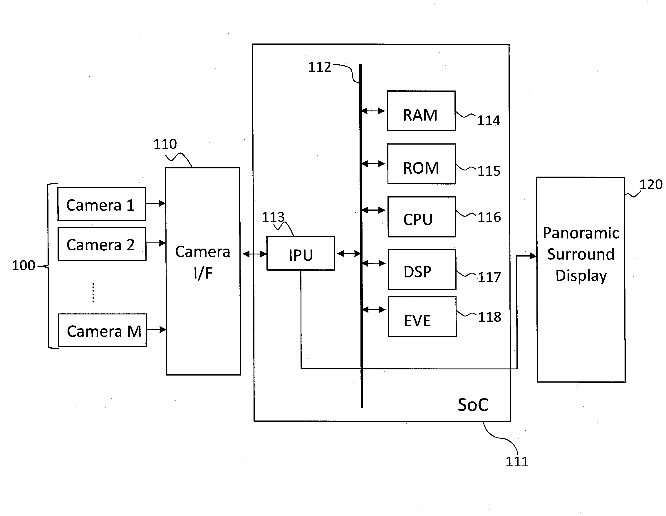
[0020]Various embodiments for the method and system of presenting panoramic surround view on a display in a vehicle will be described hereinafter with reference to the accompanying drawings. Unless defined otherwise, all technical and scientific terms used herein have the same meaning as commonly understood to one of ordinary skill in the art to which present disclosure belongs. Although the description will be made mainly for the case where the method and system method and system of presenting panoramic surround view on a display in a vehicle, any methods, devices and materials similar or equivalent to those described, can be used in the practice or testing of the embodiments. All publications mentioned are incorporated by reference for the purpose of describing and disclosing, for example, the designs and methodologies that are described in the publications which might be used in connection with the presently described embodiments. The publications listed or discussed above, below...


PUM


Abstract

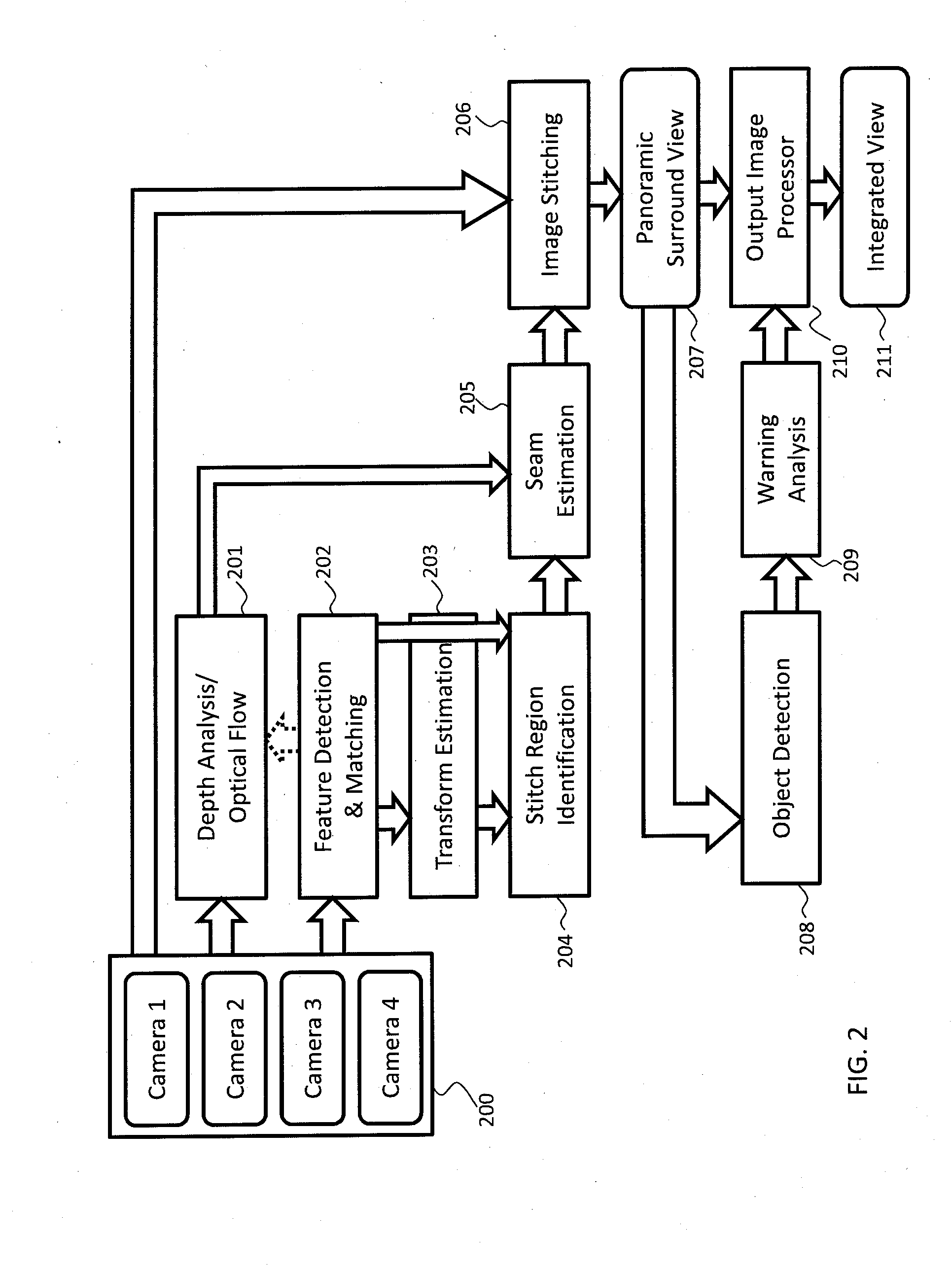
A method and system of presenting a panoramic surround view in a vehicle is disclosed. Once frames are captured by a plurality of cameras for a period of time, features in consecutive frames of the plurality of cameras are detected and matched to obtain feature associations and transform is estimated based on the matched features. Based on the detected features, the feature associations and the estimated transform, a stitching region is identified. Particularly, an optical flow from the consecutive frames is estimated for the period of time and translated into a depth of an image region in the consecutive frames. Based on the depth information, a seam in the identified stitching region is estimated and the frames are stitched using the estimated seam, and presented as the panoramic surround view with priority information indicating an object of interest. In this manner, the occupant obtains an intuitive view without blind spots.

Description

BACKGROUND[0001]1. Field[0002]The present disclosure relates to a method and system for presenting panoramic surround view on a display in a vehicle. More specifically, embodiments in the present disclosure relate to a method and system for presenting panoramic surround view on a display in a vehicle such that a continuous surround display provides substantially maximum visibility with natural and prioritized view.[0003]2. Description of the Related Art[0004]While a driver is driving a vehicle, it is not easy for the driver to pay attention to all possible hazards in different directions surrounding the driver. Conventional multi-view systems provide wider and multiple views of such potential hazards by providing views of different angles from one or more cameras to the driver. However, the conventional systems typically provide non-integrated multiple views divided into pieces with limited visibility that are not scalable. These views are not intuitive to the driver. It is especial...

Claims


Application Information

Patent Timeline
Patent Type & Authority Applications(United States)
IPC IPC(8): H04N5/232G06T7/00G06K9/00H04N5/247H04N23/90
CPCH04N5/23238G06K9/00791G06T7/0071H04N5/247G06T3/4038G06T2207/10016G06T2207/30252B60R2300/60G06T7/579B60R2300/303B60R2300/307B60R2300/802G06V20/56G06V10/16H04N23/951H04N23/698H04N23/90B60R1/27
Inventor HAN, MAUNG P.MONGA, DHRUV
Owner ALPINE ELECTRONICS INC
Learn More