Engine
- Summary
- Abstract
- Description
- Claims
- Application Information
AI Technical Summary
Benefits of technology
Problems solved by technology
Method used
Image
Examples
Example
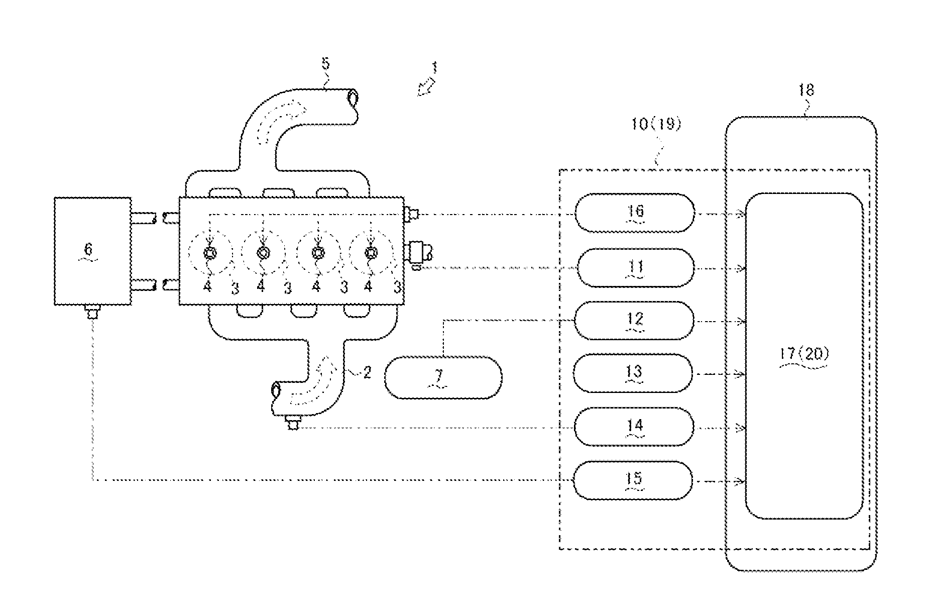
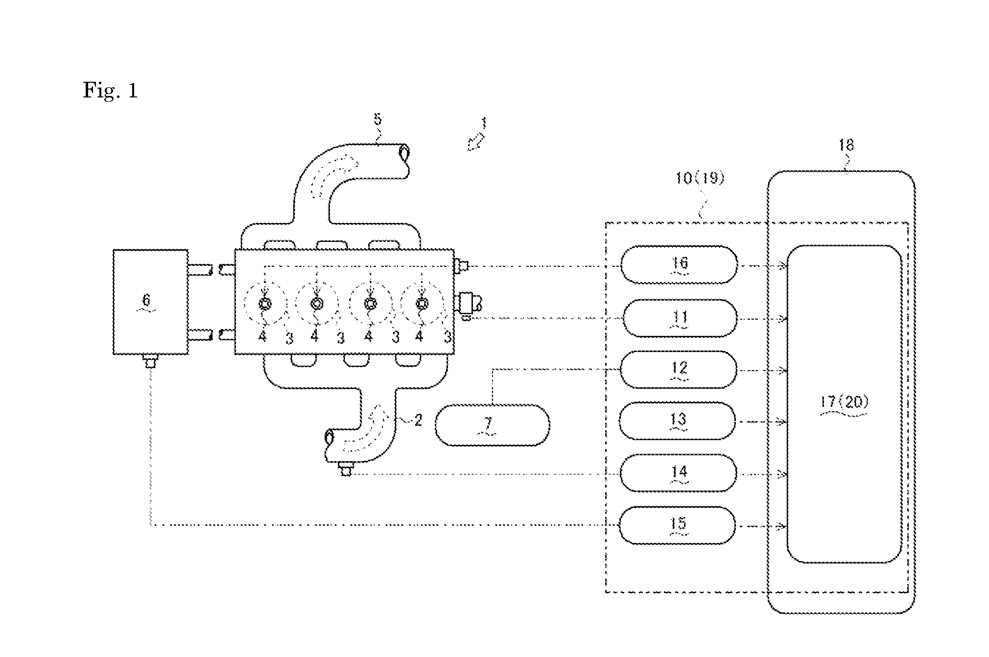
[0027]Next, an engine 1 according to a first embodiment of the present invention will be described referring to FIG. 1.
[0028]As illustrated in FIG. 1, the engine 1 is a diesel engine, and in the present embodiment, as illustrated in FIG. 1, the engine 1 is an inline four cylinder engine that includes four cylinders 3.
[0029]Regarding the engine 1, outside air supplied via an intake pipe 2 and fuel supplied from fuel injection valves 4 are mixed in the interior of cylinders 3 and combusted, thereby drivingly rotating an output shaft. The engine 1 discharges exhaust gas generated by the combustion of the fuel to the outside via an exhaust pipe 5. The engine 1 includes a fuel injection control device 10 that controls a fuel injection amount injected from the fuel injection valves 4 and an ECU 18 that controls the engine 1.
[0030]The fuel injection control device 10 serves to control fuel injection. The fuel injection control device 10 includes an engine revolution detecting unit 11 that ...
Example
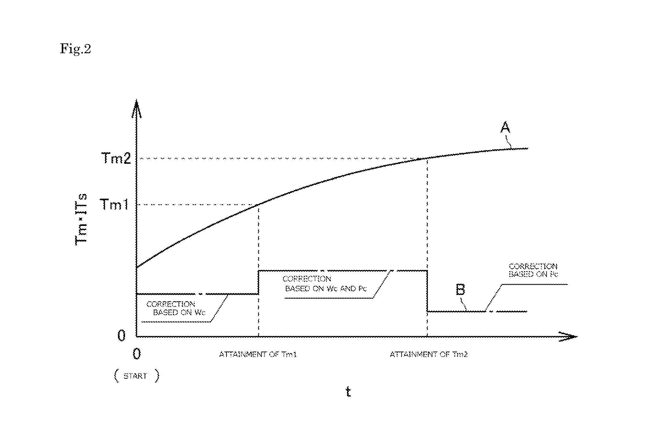
[0115]Next, the engine 1 of a second embodiment of the engine according to the present invention will be described referring to FIGS. 1 and 7. The engine 1 includes a fuel injection control device 19. The fuel injection control device 19 includes a fuel injection control unit 20 and calculates the first predetermined temperature Tm1 and the second predetermined temperature Tm2 in accordance with the outside temperature To. It is noted that the standard injection time will be described in the following embodiment, out of control modes of the standard injection time, the fuel injection pressure, the fuel injection interval, or the fuel injection amount of the fuel injection control unit 17. It is noted that, regarding the same matters of the embodiments that have been already described, their specific descriptions are omitted, and the following description focuses on the different matters.
[0116]As illustrated in FIG. 1, the fuel injection control unit 20 stores a predetermined tempera...
Example
[0122]Hereinafter, an engine 21 according to a third embodiment will be described referring to FIG. 8.
[0123]As illustrated in FIG. 8, the engine 21 is a diesel engine 21, and in the present embodiment, an inline four cylinder engine 21 that includes four cylinders 23.
[0124]Regarding the engine 21, intake air supplied to the interior of the cylinders 23 via an intake pipe 22 and fuel supplied from fuel injection valves 24 to the interior of the cylinders 23 are mixed in the interior of cylinders 23 and combusted, thereby drivingly rotating an output shaft. The engine 21 discharges exhaust gas generated by the combustion of the fuel to the outside via an exhaust pipe 25.
[0125]The engine 21 includes an engine revolution detecting sensor 26, an injection amount detecting sensor 27 of the fuel injection valves 24, an EGR device 28, and an ECU 35, which is a control device.
[0126]The engine revolution detecting sensor 26 serves to detects the number of revolutions N of the engine 21. The e...
PUM
 Abstract
Description
Claims
Application Information
 - R&D
- Intellectual Property
- Life Sciences
- Materials
- Tech Scout
- Unparalleled Data Quality
- Higher Quality Content
- 60% Fewer Hallucinations
Browse by: Latest US Patents, China's latest patents, Technical Efficacy Thesaurus, Application Domain, Technology Topic, Popular Technical Reports.
© 2025 PatSnap. All rights reserved.Legal|Privacy policy|Modern Slavery Act Transparency Statement|Sitemap|About US| Contact US: help@patsnap.com


